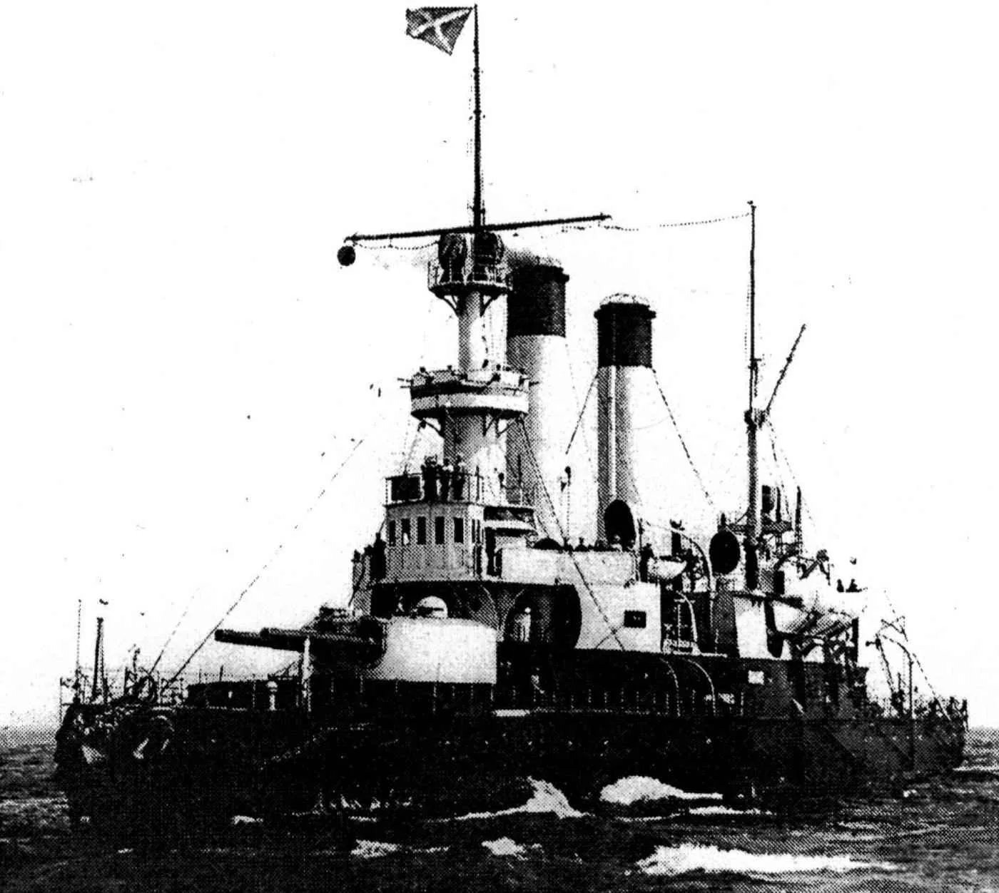
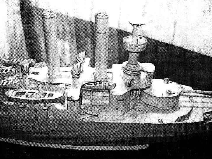
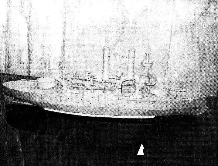
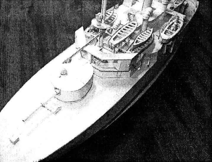
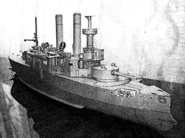
 Coastal defense battleship General-Admiral Apraksin. Scale model 1:200.
The rapid development of foreign fleets (primarily German) forced to 1890, to revise the Russian 20-year shipbuilding program (1883-1902.). A plan to strengthen the Baltic fleet in 1891-1895 he was provided, among others, the construction of armored ships with shallow draft and heavy armament, designed for operations in inland seas, and defence of the coast. Simultaneously with the elaboration of the project attempts were made to obtain information about the foreign “the latest coastal ironclads and gun-boats”. From late 1889 to June 1891 MTC under the guidance of senior naval architect E. E. Gulyaev consistently prepared preliminary designs of the armored ships with a displacement of 3850 to 5500 tons.
Comparing them with foreign, and E. E. Gulyaev came to the conclusion that “at the same deepening and displacement we may have designed and built much better protected battleship”. After approval in June, 1891, preliminary design for two-tower of a battleship of the Baltic sea (the displacement of 4100 tonnes) there was a need to increase the speed to 1 kt due to the weakening of booking (“in view of the progress of the German battleships 16 nodes”), and the installation of new quick-firing 152 mm guns.
Work on the first armored ship (February 1892-the battleships of coastal defense) began on 16 June, the second -20, July, 1892, the third – 12 Oct 1894 Ceremonial laying of the ships that have received the names of famous naval commander, “Admiral Ushakov” (Baltic shipyard), “Admiral Senyavin” and “General-Admiral Apraksin” (New Admiralty) was held on October 22, 1892″ g., 8 APR 1893 20 may 1895, respectively (the displacement on the draft 4126 t, 86,4 maximum length, width 15,9, sediment with normal fuel capacity 5,2 m, speed 16 kN at механизмов4250 power indicator L. E., a normal fuel supply 214, the full 400 tonnes). The project includes the installation of four 229 mm guns (barrel length of 35 calibers) in two towers, four 152-mm rapid-Kane, six 47-mm single-barreled, eight 37-mm Hotchkiss pedestaling and two 64-mm airborne Baranowski.
The first two ships of the “Admiral Senyavin”, as they were called in documents of those years, it was planned to enter service in the campaign of 1894 due to insufficient production capacity for the production of marine engines in the Baltic and the Franco-Russian plants, as well as their heavy workload, the Naval Ministry has ordered for them the main machinery in England. Contracts with firms “hamfris Tenant” and “Models” (respectively on 13 March and 20 July 1892) included the fabrication and erection of machine and boiler plants “Admiral Senyavin” and “Admiral Ushakov” by the summer of 1894, but two steam engines triple expansion (total display capacity of 5 thousand HP) and four agnetron boilers (steam pressure 9 ATM.) the composition of each machine and the boiler plant includes a desalination refrigerators, evaporators, etc.; established a three-blade propellers (diameter 4 m) with removable blades. The company gave two-year warranty for the main machinery, provided navigation during this period, the observing engineer of the company on each of the battleships.
 In December 1893 the Franco-Russian plant was asked to provide an order for the production mechanisms of the battleship “General-Admiral Apraksin”. Domestic marine engineering needed support, so the Naval Ministry has gone on the conclusion of the contract (20 Jun 1894), despite the fact that the cost of such arrangements on third exceeded the English. In the midst of construction of battleships began to work the first domestic testing pool (spring 1894); the tests were eight models of the ship hull of this type, and one of them is to ensure that the speed of 0.5 ties more than design.
October 27, 1893, was held the launching of the “Admiral Ushakov” and 10 Aug 1894 – “Admiral Senyavin”. Their construction coincided with the adoption of the Russian Navy guns of a new type, differing from the former the greater length of the barrel, and hence the initial velocity of the projectile. In addition, the introduction of a 10-inch (254-mm) guns instead of 9-inch (229-mm) is also due to the desire to have instead of some calibers more uniform (203, 254, 305 mm) for easy selection of the caliber of the artillery in the design of ships, the Same weapons the Military has taken to shore batteries, which had to communicate the new battleships. The decision about arming the 254-mm guns 45 calibres in length is provided by the project became almost the main reason for the large overload of battleships and delay the entry into operation (after 5 years of work). The first eight guns, ordered the Obukhov plant for “Admiral Ushakov” and “Admiral Senyavin”, accepted into production without testing prototypes. Tests in 1895-1896 years, on the Okhta sea range have shown that reducing the weight of the gun affected his strength; needed to limit the charge, and hence the firing range.
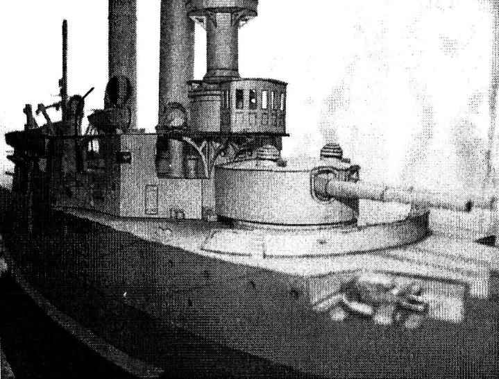
 In 1892, held a competition to design a tower installation for two 254-mm guns; participated as the Russian factories, and a number of foreign firms (Metal, Putilov, “Armstrong”, “Whitworth”, “kayl”, “Paris”, “Kane”). Won “Whitworth” and the Putilov factory, but the latter requested for every two sets a lower price (for 310 thousand rubles.), which decided the outcome of the case. On the first two ironclads artillery systems were hydraulically operated, for “General-Admiral Apraksin”, for the first time in the Russian Navy – with electric; in addition, they had greater elevation of the guns (35° vs. 15 on the first two), which increased the range from 60 to 73 cables and allowed the rate of fire of 1 shot in fifteen minutes the Use of tower installations with electric drive, without a doubt, a progressive step in the domestic shipbuilding at the time, despite the fact that the mass of each plant increased for various reasons, from 144 to 255 t, and the cost by 20%.
Booking the first two battleships were in accordance with the project. Armor belt length waterline 53, with a height of 2.1 (with water immersion 1.2 m) was for engine and boiler rooms a thickness of 254 mm with reduction to the lower edge to 127; the bow and stern the thickness of the plates was also decreased (203 mm). To protect against the trailing fire on the ends of the armored belt was put forward (203 mm) and feed (152 mm) of the traverse, from which the extremities were carapana deck (50 mm). On top of the armor belt was located armored deck (25 mm), where around machine hatch was set armor 65 mm glassy height of 0,76 m. In connection with the change in 1894, the design of the form of the towers of the main caliber of their vertical armour decreased from 203 (the project) up to 178 mm, leaving a thickness of the armor tube feed shells (152) and the conning tower (178) of the former. Even before testing the first two ironclads, it became apparent that in final form they will have significant congestion. To avoid this, the third ship decided to reduce in one and a half inches (38 mm) thick armor belt and nasal traverse, ordering them “harvialantie” and turret to make odnorodnoi.
Delivered in the autumn of 1893 from England are the main mechanisms in the summer of 1894, was installed on the ships, but the battleships were not ready for testing, so the mechanisms were partially disassembled and mothballed for the winter, that the contract provided for. Testing mechanisms on the “Admiral Ushakov” began in 1895 navigation without weapons and reservations, and the required draught provided by the water-filling part of the double bottom and side outlets. After increasing in the dock step screws (their selection of empirically – ordinary at the time the case), the ship 27 Oct 1895 came to the official’s 11.5-hour test; when the displacement 4020 t, the indicator of power machinery 5769 PS it showed full speed of 16.1 bonds.
 12 Nov 1899 “General-Admiral Apraksin” left Kronstadt for the winter at Libau and 3 h of the night when a strong storm popped up on the rocks near the southern tip O. Hogland. The largest hole area of about 28 square meters were in the bottom (12-23 FR.), through her nasal branch of the gushing water. Soon due to the insufficient tightness of the main bulkhead (24 FR.), as well as flooring of the second floor flooded and bow boiler room. In December, a victim of the accident the ship was in the ice captivity, and the message with it supported only the icebreaker “Ermak”. With the work of the rescue of an Armadillo is connected and the first practical use of the invention by A. Popov -radio. News of the position of the ship with the island of Hogland was transmitted by radio to the nearest (43 km) the Telegraph station and then further. Many proposals, sometimes fantastic, on the withdrawal of the battleship were published in Newspapers. In the end matured the plan as follows: to drill the rock hole, and lay them in dynamite cartridges. Drilling granite monolith using a diamond drill, mounted on interconnected rods with a total length of 23 m, and installed on ice machines, rotating manually, proved to be very difficult. For 10 h was able to do one hole 50 cm deep in which the diver then placed dynamite. Only after successful completion of the demolition works to “Ermak” 11 APR 1900 managed to shoot an Armadillo with stones.
During the Russo-Japanese war, all three battleships entered the detachment of rear Admiral N. I. Nebogatov heading gain was in the way of the 2nd Pacific squadron. In Libau, the ships were docking, was the installation of the rangefinders Barra and Strada, scopes, radio telegraphs. February 2, 1905, the squadron with the help of the icebreaker ‘Yermak” reached the outer Harbor.
The campaign has become a serious challenge not only for crews, but also of battleships built for inland seas; when fresh the weather in the ocean, they started to dig his nose, taking the wave to the bow of the tower; when travelling against the waves, the speed fell to 1-3. uz. Storm in the Bay of Biscay roll reached 28°, the “General-Admiral Apraksin” began to leak rivets and seams of the Board, in residential premises of officers and crew of the accumulated water. Transition in the tropics for not adapted to long voyages in this climate, the ships became incredibly difficult. Taken beyond all norms coal filled up all available space up to the officer. Only in this way managed to increase the fuel capacity up to 550 tons, allowing a cruising range has reached 3400 miles 8-9-node move (coal consumption of 30 tons per day). Due to overload armor belt were completely under water, the displacement of, for example, “Admiral Senyavin” exceeded 5400, etc
April 26, 1905, after 83 days hard way, the detachment of rear Admiral N. I. Nebogatov joined the 2nd Pacific squadron in the Bay of van Fong (now Vietnam). Almost immediately, the pipe arrived ships on the model of the 2nd Pacific squadron of Vice-Admiral 3. P. Rozhdestvensky was repainted from black to yellow (with black edges on top), and the mast is light ball.
All three of the battleship participated in the battle of Tsushima on 14-15 may 1905, In the result obtained in the daily battle damage “Admiral Ushakov” behind the squadron, and its commander, captain 1st rank V. N. Miklukha-Maklai (brother of the famous Explorer of New Guinea) decided to break through to Vladivostok. The following day the Japanese cruisers “Iwate” and “Yakumo” caught an Armadillo, which, after an unequal 30-minute battle he received severe injuries; the officer declined the offer to surrender and died with the ship. The remnants of the 2nd Pacific squadron under the command of rear Admiral N. I. Nebogatov, may 15, surrounded by superior enemy forces. Dagelet, were forced to surrender. Renamed “Okinoshima” “General-Admiral Apraksin” ten years was used as a training ship, and then Blokhina (excluded from the lists of the Japanese fleet in 1926), for two years survived his “Mishima” -former “Admiral Senyavin”.
That is the sad fate of those battleships and many other ships – the participants lost tsarist autocracy inglorious war. Intermediate the shipbuilding program in 1895 (for the period 1896-1902.) provides for the construction of four battleships of coastal defense. However, the operational-tactical views of the management on the use of the Russian fleet has changed, with the result that it was decided to build only one such ship. In December, 1899, was approved the draft design of the battleship with a displacement of 5300 tons and in September of the following year even followed the order to begin its construction, however, shortly after the breakdown at the Plaza in the works were suspended and never resumed. Further development in the Russian Navy battleships of coastal defense is not received.
Assembly recommendations
The model is not complicated to manufacture, but will require special care in the Assembly of some parts. Before beginning work read carefully the description, details and their location on the leaves. The Assembly of parts is carried out in ascending order of numbering. The bottom after Assembly it is recommended to Prime and paint, screws and a binnacle compass cover bronze paint. For best effect, suggest to make full use of retouching – joints, sections, and visible from the outside of the reverse side of ferrous parts should be shaded with black ink. Scale for the manufacture of fore – and mainsail-mast, which have contraction on a cone, it is recommended to use thin wooden slats. An additional effect of the model will give the installation of glazing in wheelhouse, guard railings, backstage pipes and rigging. For the latter, instead of the traditional thread it is better to use a thin fishing line with a diameter of 0.1 -0.15 mm black.
Legend:
Assembly model
Details of frame P1-P2, /1-U2, W1-W11, S1-S4 are glued to cardboard and cut out. The frame is assembled according to drawing. Before Assembly should whittle away at these places the edge det. P1, V1-V2, W4-W5. Reassemble in the following sequence: by using a gluing S1 to glue children. P1-P2, then install with glue ribs W2-W10 and the waterline V1-V2. After installation deck (det. 1-3) connect det.V1V2 S2 by gluing, bottom to glue ribs W1 and W11. Previously in the deck (det. 1) you should cut holes chain fairleads and puncture the marked points for installation of handrails and templates. During Assembly of the frame should follow to avoid distortions.
Before gluing the plating of the bottom (det. 4-15) and sides (det. 19-21) on the edges of the frame should be glued strips of thick paper with a width of 5-6 mm. Det. 15 to glue on the end of det. P2 between children. 13 and 14.
The anchor Assembly niches (det. 16-16d) are shown.
The Assembly of the boards begins with the bonding of side add-ons (det. 17-17b) to Spartaco (det. 3). Before gluing the sheathing Board (det. 19) from below to the holes in the deck to glue the chain fairleads (det. 19b), rolled painted side on the inside. Det. 19a is glued to the unpainted side of the children. 19 before gluing the sheathing to the frame.
Navigator’s cabin is glued of children. 22-22A and is attached in its place. Assembly det. 23 shown in the figure. Det. 24 and 27 to stick to Spartaco (det. 3), qunicy (det. 24A, 27A) can be glued later before you install the bridge (det. 33).
Covers tubes (det. 25-25d) are collected in accordance with the designations on their parts and stick to Spartaco.
 Assembly of the keel of the talus (det. 28) are shown. From the unit with bilge keels (det. 29) cut the painted part, stick the keels on the cardboard and glue it at the bottom. Assembly Davudov and screws (det. 30) shown in the figure. The hub of the rotor blades (det. 30d-30g) can be covered in bronze paint. Rudder (det. 31) is going on the picture, and glue it better at the end of the project.
Before installing the bridge (det. 33) should be installed underneath the templates A1 and A2, locations of which are marked points on sparteca (det. 3) and on the bridge. On the reels of a view (det. 32) in neat rows to wind the thread to the level of the front of the rim.
Bridge (det. 33) glued to cardboard, glue the bottom to det. 33a. Their total thickness should not exceed 0.5 mm. On one of the sheets are black stripes wrapping the edges of the bridge, their use is recommended after the installation of the bridge and the connection of the wings with covering (det. 36). Ladder (det. 34) to glue down the front of the bridge down into the side of the stern.
Before gluing the covering (det. 36) should be installed in its place a 47-mm guns (det. 35, templates, AL-A4). Det. 36A are bonded to the respective places children. 36.
Det. 39 glue the bottom in front of the bridge. Assembly det. 40 shown in the figure.
Aft of sparteca (det. 3) glue the covering (det. 42). Det. 43 folded and glued, glued on its place from below to glue knize (det. 43A). From the sides to glue the covering (det. 44), protruding edges of which the first unit det. 44a-44b. Det. 45 glued on the appropriate place det. 42.
Assembly det. 46 shown in the figure.
 Pillers bridge to carry the pattern A5. Top stick det. 47-47A. Ready pillars to set the marked points in the field for about 23 children. Then glue the aft bridge (det. 48-48A) and ladders (det. 49).
The Assembly of the conning tower (det. 50-50d) shown in the figure.
The base of the foremast is collected from children. 51-51 E. One of the parts 51A should be glued inside the bottom side of det. 51, the second inside det. 51b. Assembly det. 52-54 are shown in the figures. Det. 52s-52d can be painted in bronze color. To det. 55 from the back side to glue children. 55A. Assembly det. 56-57 shown in the figures.
The pipe going from det. 58-61. Their Assembly is shown in the drawings, a tube in the incision in the picture from the templates.
Deflectors are collected from children. 62-62b. The inner portion (and similar parts 63, 73, 76) should be painted red. The line of junction of the tubes of the baffles are located in the front, as shown in the figure.
Rostra Yala (det. 66) after cutting to shape shown on the pattern A8. The template A8 glue to the inner side. To the walls of the superstructure (det. 17) with det. 67 to glue the davits (pattern A9).
Yaly glue of children. 68-68(according to the picture. Slits in the sides to glue the inside strip of thin paper or tracing paper, inner part paint. Yaly is ready to install on rostrakh using keel blocks (det. 69). Figure I identifies the first keel blocks away from the nose, digit II, the second (that goes for the rest of the keel blocks in the model).
Parking lights (det. 70) to glue as illustrated. Det. 70A-70Ь painted in red (left side) and green (starboard) colors. Ready lights and ladders (det. 71) to stick to the bridge (det. 33) to be indicated on the General drawing.
The Assembly of the platform of Kompas (det. 72) shown in the figure. A ready platform to be installed on the bridge (det. 33).
Skylight (det. 74) and the rostra (det. 75) going through the image. When assembling booms four nepodlinnyh on the reverse side det. 75C glued in the marked spot to corner posts booms and the two glued in the same places to the middle racks. After Assembly and glued the booms to Spartaco (det. 3) glue vents (det 76) and the keel blocks (det. 77) on which to install boat (det. 78). The two remaining lifeboats at the end are hung on the davits (templates A25) as shown on General drawing.
 Det. 79-80 stick to these sparteca (det. 3). The top is glued det. 79A and 80A, respectively.
The keel blocks boats going by the figure of det. 81-81 S. First attached children. 81-81A, then the top is slightly bent death. 81b, the front edge of which is bent tweezers.
When gluing the keel blocks (det. 81с) you should make sure that they were glued properly, because one side of each cellblock tapered down, following the form of det. 81b.
Assembly davits boats (det. 82) are also shown in the figure. Det. 82g should be glued to the davits starting from the top, the lower end is bent to cover the end of the davits. Det. 82i can be made of cardboard, but better to do it from the wire pattern A11. Ready swivel wheels attach to the axles (template a10) and install in its place.
Boats’ collected from children. 83-84 as shown, and glued into place.
Barges (det. 85, 87) and the whaling ships (det. 89) are also collected, as shown in figure Yal (det. 68) and are mounted on the keel blocks (det. 86, 88 and 90, respectively) according to the General drawing.
The mainmast is collected from children. 91-94 pattern among templates. On-site (det. 92) install floodlight (det. 93), the collected pattern. Arrows (det. 94) you can stick in any direction: either in the feed (such as figures), or deployed on 180 degrees – in the nose.
Bow tower is collected from children. 95-102, the General form shown in the figure. Det. 97Ь to stick to the underside of your children. 97A (cardboard not to stick!). Det. 98A roll the coloured side inside. The incisions in the roof of the tower (det. 98) to glue strips of tracing paper or thin paper.
Aft turret (det. 103-106) is going the same way.
Build the top of the foremast (det. 107) shown in the picture from the templates. 37-mm guns (det. 108) are collected on the pattern and stick into place.
Det. 111 to glue on 3 pieces. and slightly sanded the edges. Assembly det. 112-115 shown in the figures. To det. 116 stick det. 116A. In its place install det. 117C templates A19.
The breakwater is collected from children. 118-118h. It glued together the parts 118 to stick children. 118a-B, and after installation, glue knize (det. 118с-118h) and ladders (det. 119).
Scuppers (det. 121) to glue into place on the deck, as shown on the drawing. Assembly of cleats (det. 122, 124) and vent heads (det. 126) shown in the figures.
Werpy (det. 127,129) are collected on the pattern and stick into place, as shown on the drawing.
120-mm gun roll of det. 128-128a and glue into place.
Assembly det. 130, 132, 134 shown in the figures. Det. 135 to glue on 4 pieces, the outer edges sanded to give a rounded shape. In the inner part of the paste of children. 135A so that it forward by about 0.5 mm.
Anchors going on the figure of det. 136-136d and templates A23. Ready anchors are glued into place, as shown on the drawing, and from them through the fairleads (det. 135) to the spires (det. 115) extends pattern made by the anchor chain. The end of the chain is put in the hole in the det. 116.
Assembly det. 141 shown in the figure. When gluing the aft of the crest (det. 146) its upper part to glue on the back side of the building. 146a.
Final Assembly of the model is in production patterns of the mast fore – and main masts (templates A30-A31) and the installation of rigging and rail fencing. The scheme of the rigging shown on the drawing, and the patterns of the masts indicated the attachment threads (if they are marked as R/L, this means that two threads, on the sides, unless noted – one in the centre).
In the model three types of rails (marked as R1-RZ), which are installed as build relevant components. Their location is shown on the General drawing. The rail R1 is installed on the deck (det. 1-2) and sparteca (det. 3), and searchlight platform of the mainmast (det. 92). Rail R2 is mounted on the compass sites (det. 56 and 72). Leer RZ are installed on the fore and aft bridges (det. 33, 43, 48) and the searchlight platform of the foremast (107b). Please note that the cutouts of the bridge over the covers, pipe racks handrails fastened on the outer side, as indicated in the point on the det. 33. Therefore, the front rail in this location shall have a height of 5.5 mm instead of the usual 5 mm to accommodate the thickness of the bridge.
Stand for the model is collected from children. 152-152с. Det. 152 and 152b are glued to the cardboard, cut and glued together. The edges are pasted over det. 152a and 152с respectively.
Enjoy your work and enjoyment of the result!
The materials to build a model BATTLESHIP APRAXIN (download)
Recommend to read
 NORTH LAGUNA
There are few enthusiasts, capable in difficult conditions to undertake the construction of a homemade car. To undertake and perform the scope of work for the design, construction and... DEL’TALET ON A LEASH
A kite is considered to be the grandfather of modern aircraft. This harness motorless soaring leader was the first aircraft in the so long ago, when there was still such thing —...
