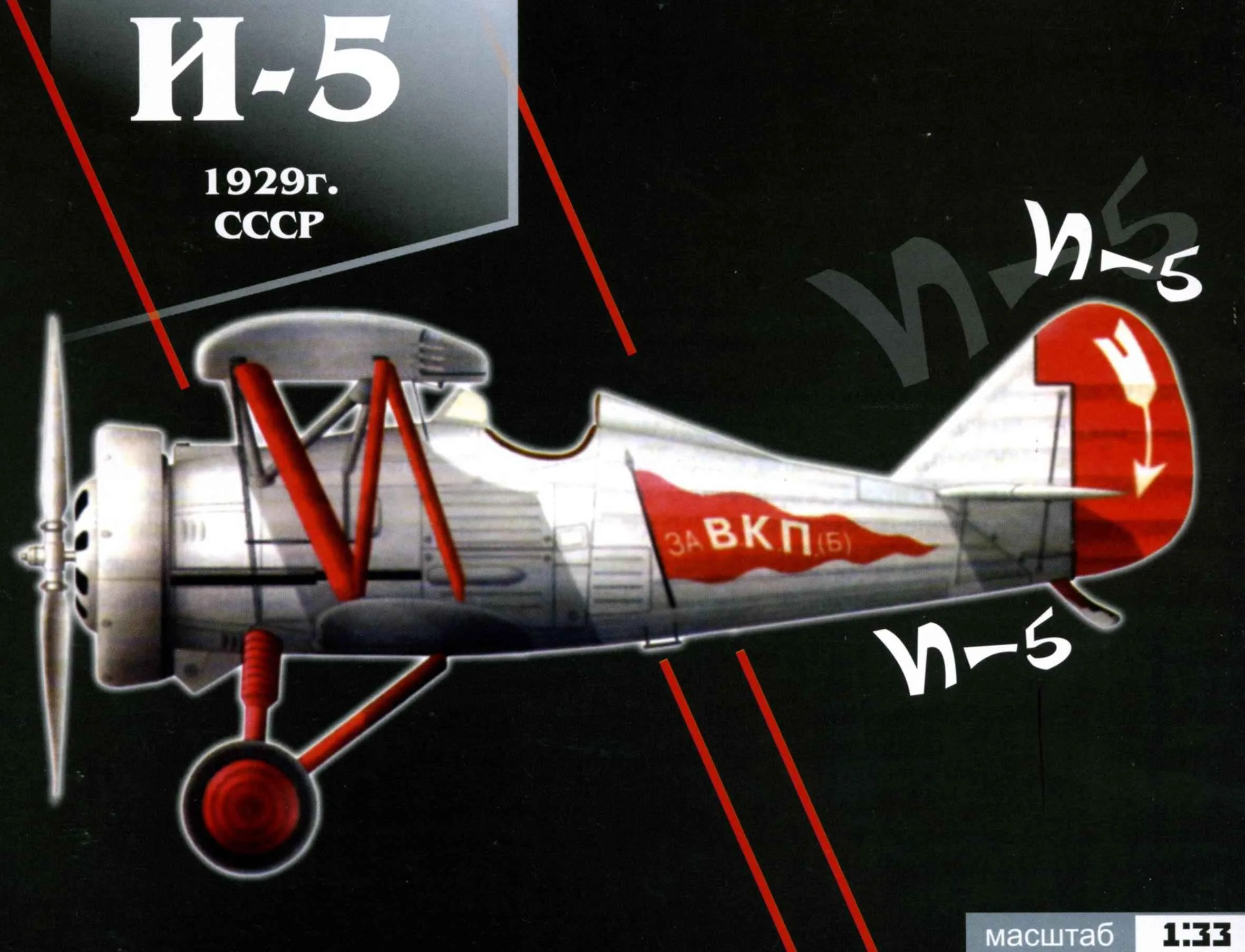
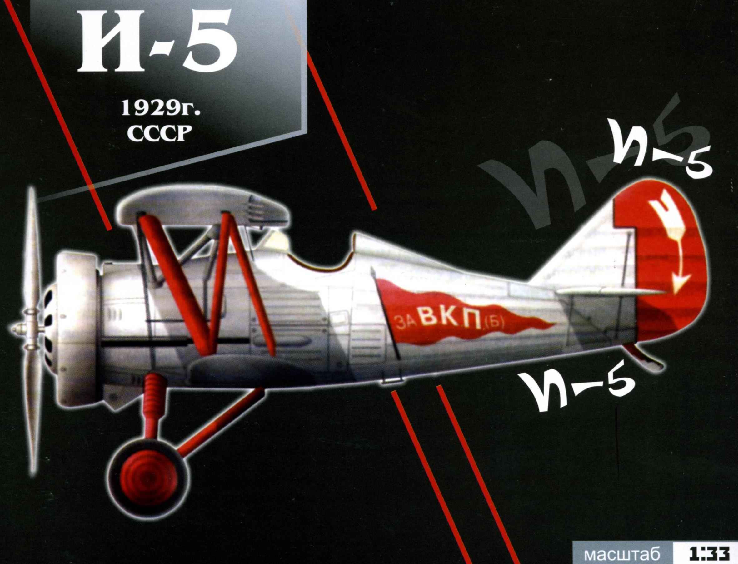
 FIGHTER I-5. Scale model 1:33.
The history of this car, dubbed the I-5, began in the summer of 1927, when Polikarpov developed a preliminary draft of the fighter under the British motor Bristol “Jupiter” is one of the best in those years of power density. This gave the opportunity to provide good maneuverability and rate of climb. Technical Council Aviatrust Polikarpov suggested to consider the inclusion of a new fighter in the prototype development plan and approached the BBC with a request to present to him their tactical and technical requirements. Design And-5 plan had to be completed in November 1929: in October of next year, it was required to produce to the test.
After receiving the task, Polikarpov and Grigorovich separately from each other and performed sketches the General form of the future aircraft. The most significant projects of the two designers differed relative to the tail section. In Grigorovich behind the cockpit the fuselage is immediately switched into the cone (as then it did – -1 and SP-1). Found a more promising option Polikarpov, largely repeating its projects I-5 (1927) and 6 (1929). Less than two months a small team of OKB designed the new I-5, which, like most fighters of that time, was polyterpene, i.e., a biplane whose lower wing is significantly shorter than the top (swipe the top -9,65 m, and the bottom of 7.02 m).
 The new fighter received from the combatant pilots a positive evaluation. It was noted that takeoff and landing is simple, the plane can take off from small platforms, has good maneuverability, stable in flight with the engine and planning, easy to manage (load on the handlebars is small), good dives. Not caused I-5 sharp objections and the ground staff – access to the main parts of the machine was quite simple. Even complex hood of the engine and the fully snimatsa in just 8 minutes. Of course, it was discovered and disadvantages, most of which was related to propeller installation. In the report on the military tests indicated that the candles do not stand up to prolonged operation, the wiring to them “throws” the oil, the exhaust gases penetrate the cockpit, poorly placed fuel pump. Some claims are applied to the airframe But all these comments have not spoiled the overall good impression, and the outcome of military trials was the conclusion: “the I-5 can be adopted for the supply air”,
I-5 occupies its place in the history of Soviet aviation as the first mass domestic production of fighter aircraft. It trained many pilots who have brought the country glory in the great Patriotic war. Yes, and the I-5 honorably fulfilled his last duty in unequal combat with the enemy. No I-5 in our country is not preserved,
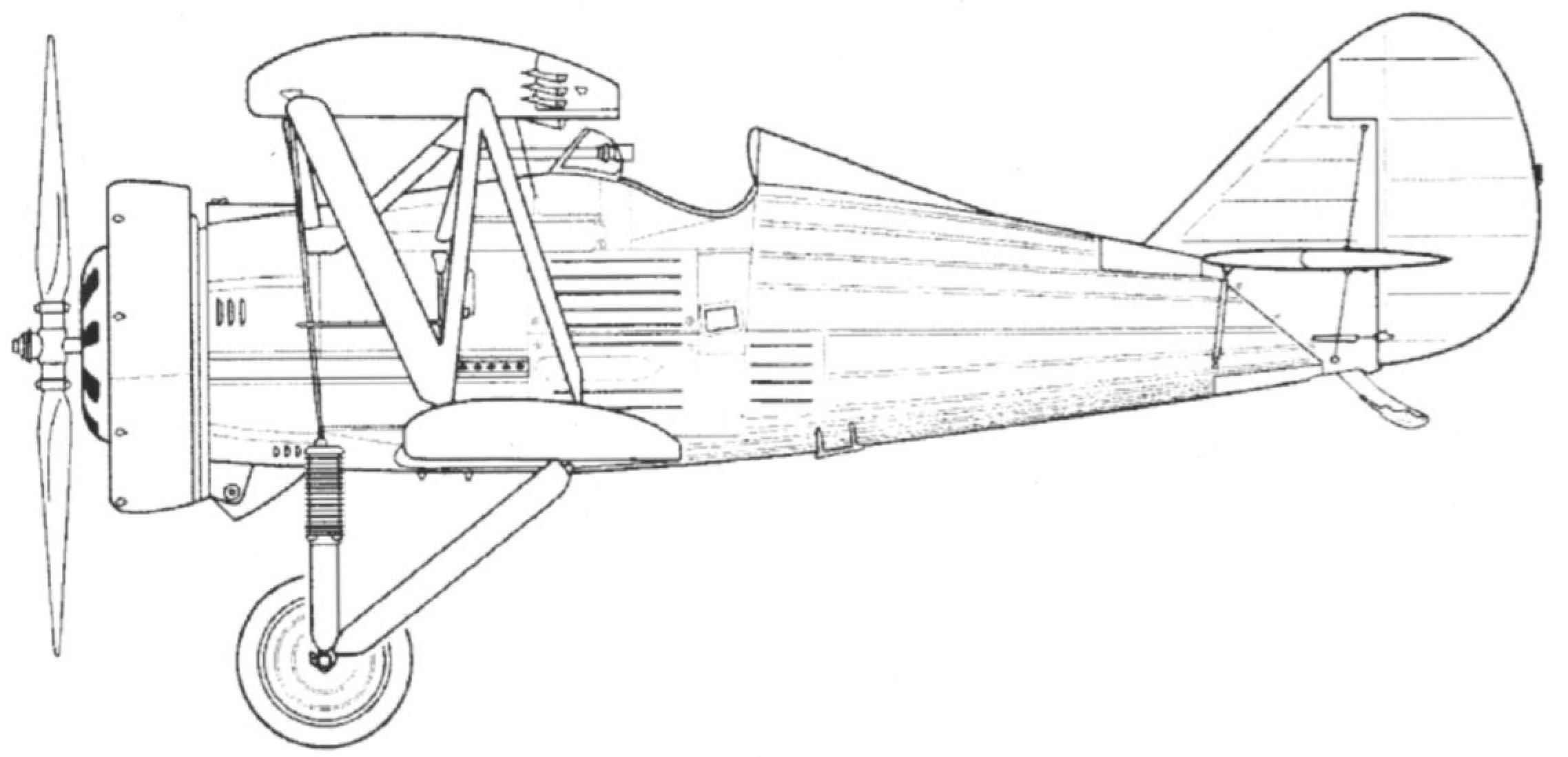
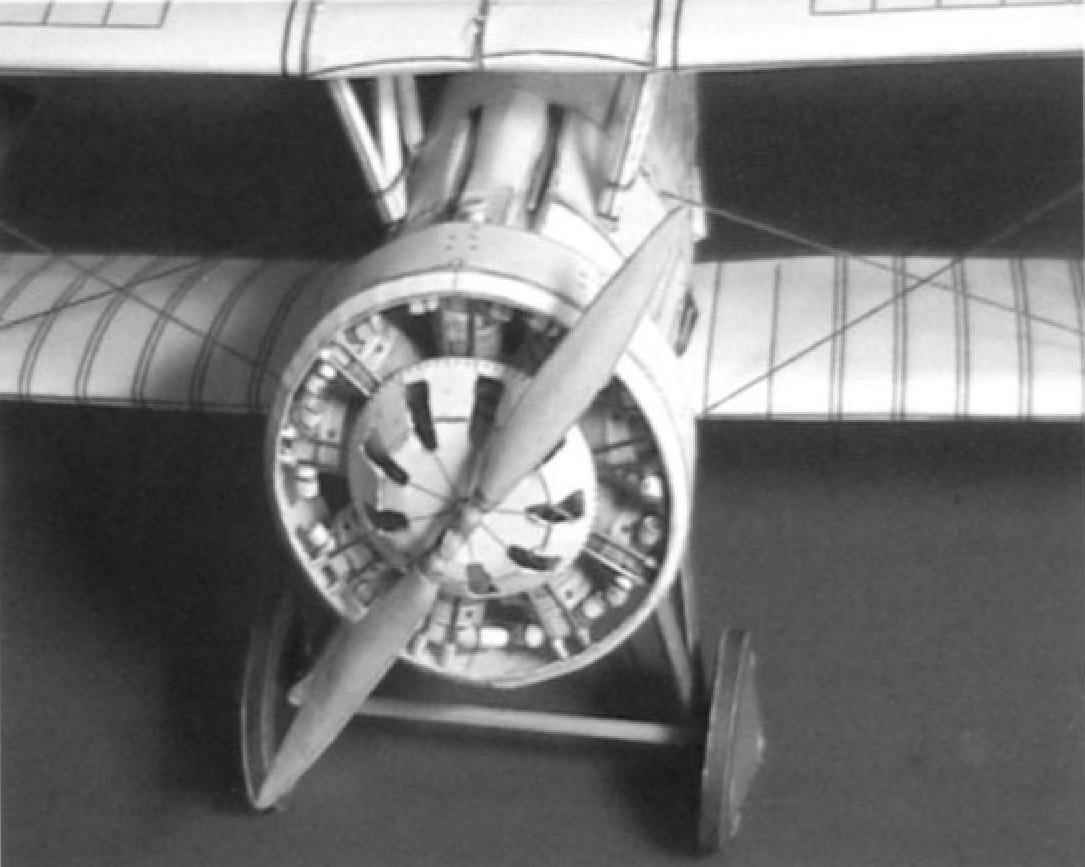
 The I-5 had a mixed structure: some nodes – metal, part wood. The frame of the fuselage was welded from steel tubes of variable cross section and was a four-sided shape. To improve the aerodynamics of the car on a tubular frame was prikladyvala the outer frame of duralumin profiles In the forward fuselage were installed to support the stringers and frames from steel tubes. The last compartment of the fuselage under the tail had a removable duralumin fairings for inspection of the shock absorber crutch. The pilot seat with a Cup under the chute of corrugated duralumin. Biplane box had an area of the bearing surface 21.3 m?. The upper wing consisted of a center section and two outer consoles. Dural wing connects with the fuselage-shaped racks made of profiled duralumin tubes. Console both wings were made of wood. Their socks to the front pangeran trimmed with plywood, as well as the top of the root parts of the lower planes between the spars. The frames of the tail, rudders and ailerons – aluminum, siding – painting. Landing gear equipped with shock absorbers 16 of the rubber washers having a thickness of 20 mm each. Pneumatics, copes primeapes two types 750X125 mm and mm. 760×100-5 the engines were installed “Jupiter/!” or M-22, 480 HP Air screw ø2,7 m dural, popieranie popusti. Step was regulated on the ground, his blades had two fixed positions. Coca, the hub of such a screw does not have. The mass flight of I-5 ranged 1336-1355 kg fuel capacity was skuchal 205 litres of petrol and 40 litres of castor oil. Armament consisted of two machine guns PV-1 7.62 mm Ammunition – 600 rounds per gun. The design of a fighter is allowed to install two of the same poemata, or hang two bombs of 10 kg each.
Top speed And-5 – 280 km/h, service ceiling – 6000 m. the Time to complete a turn (agility) in the horizontal plane is 10 s. the Propulsion system – motor, M-22 with a ring Townend – was so successful that almost became a model: it ispolzovatj many aircraft designers of the time.
 PERFORMANCE CHARACTERISTICS OF PLANE-FIGHTER-5
Year of issue — 1929
Motor power, HP — 480
The scope of the upper wing, m — 9,65
Length of aircraft, m — of 6.51
The wing area, m2 -21,3
Take-off weight, kg -1336
Nominal speed, km/h -286
Ceiling, m -7500
Flight range, km — 620
A climb of 5000 m, min -10.1
Time of turn, -9,5
Armament: quantity, calibre, mm —2×7,62
Assembly instructions
1. Before beginning Assembly, carefully read the installation drawings and diagrams
2. Use paper and cardboard according to legend.
3. Parts of the skeleton should be cut along the bounding black lines, trim and color details along the border line color.
4. When gluing the frames are advised to spend at the ends of the part with a blunt knife or sandpaper.
5. Details that need to curl into a roll or cylinder, for better twisting route through the edge (corner) of the table
6. All the white ends of the color detail (paneling glue) you need to paint the markers of the corresponding color.
7. For the best bending parts bend lines, slide a blunt knife on the back side of a part bend line.
8. When assembling, consider the following notation: V1 – the main part;
B1.2.-1.5 accessories in the Assembly, giving a common part;
The Assembly model is split into several stages:
1. Mounting of the skeleton of the model nose and tail parts.
2. Installation of the cockpit seat, belts, controls.
3. The cladding model.
4. Installation of the wings, elevators and rudder
5. Installation of racks, braces, chassis,
6. Mantadigital.
ASSEMBLY MODEL
1. Monticellite Fig.1-2.
The skeleton of the nose of the model consists of the following parts – a-AL. When cutting ensure that not to go beyond the details indicated by the solid line. Details pasted on cardboard 1 MLM. Then in the slots Det.And individual Children.A1-AZ. The lateral edges (Det.A1-Ar) affixed to the structure in the last turn.
The tail part consists of the following parts-C5. First, in the slot Children.With individual Children.C1-5, and then insert the side ribs C1, CP. Then you need to det,C5 pasting additional parts A, b, C, D.
2. Installation of cockpit Fig.3-18a.
Gluing the cockpit begins with the bonding of the foot controls (Det.P1-P7), compass (Det.K1-K4), control levers (Det. 1A-1f, 2A-2b, For-Зb), side panels (Det.S1, S1.2), helm (ДетR1-R5). The order of bonding of the listed parts shown in the Assembly drawings and the special difficulties does not cause. Please note that when gluing the leverage they need to stick to one another without podleski cardboard. In addition it must be remembered that of the side panels, only the inner details of the first unit with cardboard in them to make the appropriate cuts, and then glue the outside Next, cut the front and rear frames (det,B1, B4), medium frames (Det.B2, VZ), mount the dashboard (Det.T1-T4), cabin floor (Dec.2). These items should be glued to 1 MLM cardboard.
The cutouts in the front bulkhead (B1) insert the mount of the dashboard (T1-T4), side panel (S1 1., S1.2), and gender (S2). Glue the rear bulkhead (Det.B4). On the floor of the cab, glue on already collected by us foot controls and a compass. For mount dashboard adhesive dashboard, installed the steering wheel on the right side glue tape flares (Det.B2.2.R, B2.2..p). Item B2.2..R before bonding, it is necessary to twist into a tight coil.. Then on the left and right sides adhesive shelf mounting machine guns (52.1), Glue the frames mounting the pilot’s seat (Det.B3.2A, B4.1). Glue the middle frames (Det.In.Z., B3.1.). Collect machine guns (Det.P1.1-P1.4), but the guns on the shelves are not installed. Collect the pilot seat (Det. 1.1.-1.5) and set him in his place. Next, collect the headrest of the pilot (Det.OT.Z.and-OT.Z.with) and glue it to the frame B3.2. Collect bombs(Det.Вм1-Вм7) and glue them to the floor below.
3. Glue the nose, tail and cockpit into one unit – 18b.
4. The cladding Fig.19-21.
The skin of the aircraft begin to glue with the bow and follow in the direction of the tail the oil Tank (Det.Ms.2.1-2.3) is glued after gluing the planking of the bow. From the bottom glue the air intake of the carburetor (Det.Ml) from the edge of the front bulkhead on the glue line trim Then glue mine top guns (Det.Ob.1.), and mines lower machine guns(Det.Оb2.1.R), and set respectively the upper and lower machine guns. Now continue to glue obshivka in the tail. When mounting the plating of the cockpit you must first on the inner lining (Det.Оb2+3) glued on the external side cladding of the cockpit (Det.Оb2, ОbЗ), cut undercuts bomb holes and close them with transparent tape and then glue the glue and then stick the trim on the cockpit.
The details of the fairing machineguns (ОbЗ.2) stick to the skin in the least. Item Ob.3.1 R(Venturi) should be rolled into a tube and glue on the right side, in the circle below the neckline in the cockpit. Glue the cockpit (det Оb4.1).
Further details sticking the casing in the direction of the tail of the aircraft. Please note that vdet. Оb4, 5, 7, 8 you will need to make cutouts in place
5. Installation of the wings, elevators and rudder Fig.23-26.
Gluing on the wings, rudders and elevators is shown in Fig.21-26 and the special difficulties does not cause. Please note that details of the skeleton elevators (Rv) are glued to the cardboard of 0.5 MLM. Parts of the skeleton of the wings, rudders (Kv, Xv) glued onto the cardboard 1 MLM. Suggest ends of the handle parts with a dull knife for a better fit of the trim parts. Covering moving parts glued in the following order: first, You need to slot in the casing to thread the skeleton nepodvizhnoi, and then according to the figure to insert the skeleton of the rudder, Aileron, elevation, threading guide axis, and then glue the trim.
6. Installation of racks, chassis, braces Fig.29-30.
When gluing struts of the wings (St1, St2), You need between scans plating racks, insert the required length of floss and then glue the pillars sweep the Edges of toothpicks necessary to sharpen. After the glue has dried, assembled the stand first glued to the upper wing of the plane, then put the strut in the fuselage, and then struts to the lower wing of the aircraft. In the fuselage and lower wing need awl with a thickness of 2 MLM make holes for mounting racks.
Landing gear consists of parts (Sh1 – Sh6). First collect landing gear (Sh6) and also empower them with pieces of toothpicks. Before mounting the chassis thorn 2млм make the holes for mounting the landing gear. Next, glue on cardboard 1 MLM disks (fleT.Sh4, 5), which make the hole under the mount axis. Glue the discs together. Basically, the tyre drives (flerShl) and with inner and outer side of the adhesive rim(Det. Sh2), and then threaded axle (Template – Тг1) and glue on the outer side of each wheel caps(det. Sh3 3.1.). Completed the Assembly of the chassis pulling the braces from left front to right rear and from right front cool rear racks..
7. Installation of the engine. Fig.31-35.
From the beginning, you need to cut the side panels (Det Da-Dc) engine and stick them on 1 MLM cardboard. It is also necessary at this stage to cut in children. Da, Dc is the hole for the screw shaft, and then assemble the crankcase according to Fig.31. Give time to dry the crankcase and start the gluing of the cylinders of the engine. When gluing the cylinders of the engine follow this procedure: first, twisted in a coil lower part of the cylinder (Det. D1Ь), then glue the upper part of the cylinder (D1c) is also twisted in a roll Bottom and cover brehnya (children d 1A, Did) glue in the last turn. This way they glue the cylinders to the crankcase (Fig.32). Then merge into one unit det. D4 and D3. Please note that vdet D4b, until her bonding with a needle to make holes. Next, glue the pipe (fleT.D2a-D2c) First, you need to glue together det.02с, and after drying priceit to Det.D1f. Exhaust pipes (ДетD2d) at this stage does not stick. The holes in det.D4b. plug-in guide (template – Tg.2) and glue them to each cylinder respectively
Cabot motor is glued together in that order. First You need to glue Children.KD.Z gluing, cut out the holes for the engine cylinders and pipes. Holes for Shahi machine guns at this stage is not cut. Further details of Kd.1.3 glue det-Kd.l .2 and are completing the Assembly of the front part of the hood sticking children.Kd1.3. The front part of the bonnet neatly put on the engine and glue the rear part of the hood Kd.1.4. Now cut the holes for mine guns and glue Children.Kd.1.3,a respectively with the left and right sides. Assembly engine complete adhesion of the annular cowl (Det.K1.1., K1.2.). The engine Assembly is glued to the plane).
6. Mounting screw Fig.36.
Screw assembled according to Fig.36 and the complexity will not cause. Suggest to conduct a sweep screw on the edge of the table to give them a convex shape. The axis of the screw (Det.Vt.H) first, screw on wire (Template Tgz.) and then glued according to the installation drawing.
Finish the build gluing the pegs (Template Тг4.) with the right and left sides of the aircraft at the bottom of the hull.
Good luck with your bonding and enjoyment of the model.
The materials to build a model PLANE-a FIGHTER I-5 (download)
Recommend to read
 COLLAR FOR ROLL
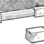
Brought home the new bulbs, and boxes from them decided not to throw it: adapted for the storage of paper rolls is Worn on a rolled up drawing, they do not give him to unfold, and the...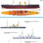 “RICH SHIPS” FOR THE “POOR RELATIVES”
4 Dec 1867, took place at the first sight unremarkable event that opened is actually a completely new era in military shipbuilding. The stocks of the steel company "William Armstrong and...
