
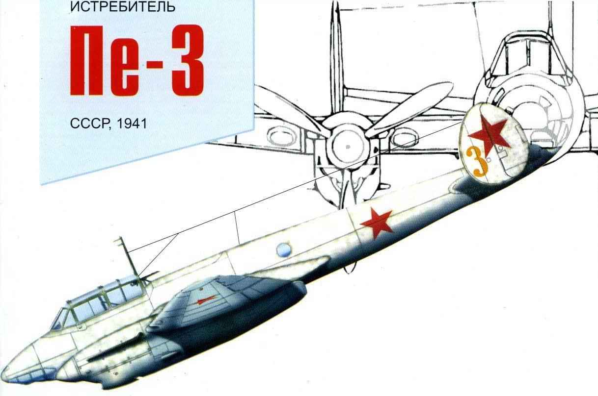
 FIGHTER PE-3. Scale model 1:33.
In the summer of 1941 the Soviet air force was required loitering interceptor, designed to combat bombers and scouts of the enemy. To do this, the aircraft was only possible on the basis of serial cars. So we stopped at the “last fighter” front bomber the PE-2.
The decision of the State Defense Committee dated 2 August 1941, Moscow aircraft factory No. 39 was ordered in the period until August 6 to make a fighter variant of the PE-2 bomber. Only four days were allocated for work related to radical change in many important systems, e.g., fuel, rework weapons facilities and radio equipment. And here on 7 August, the first prototype twin-engine fighter later designated PE-3, in accordance with the existing order – to give the fighters an odd ordinal numbers in contrast to the aircraft of all other assignments – took to the air under management of the factory test pilot, major Fyodorov. You can hardly find in the history of aviation another example of such efficiency, because between ordering the machine and output it to the state tests took only seven days.
 The fighter stepped up a few offensive weapons, placed in the forward fuselage for more gun BK 12.7 mm ammunition 150 rounds. Thus, bow-missile setup of the prototype consisted of two heavy machine guns BK and one ShKAS with 750 rounds. Serial PE-3 machine gun THTAS removed, but increased the ammo for BC to 250 rounds per gun.
The top turret of the Navigator with a machine gun ShKAS has no changes from PE-2. As ago-down to fire there was no one, remembered spent for high-altitude fighter “100” fixed tail installation ShKAS machine gun with 250 rounds bicompactum, which was mounted in the tail cover of the fuselage. Bomber installation radically simplified.
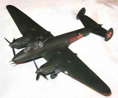
The prototype, converted from the already completed production of PE-2 bombers, had a serial number 391606 (which meant sixth plane the sixteenth series of the plant № 39), weighed for 7860 kg. empty Weight was 5890 kg. On the tests in NII VVS red Army managed to obtain the following basic performance characteristics: maximally speed at an altitude of 5000 m – 530 km/h ceiling – 8800 m and a maximum flight range – 2150 km. this data is considered satisfactory, and on August 14 factory No. 39 was ordered to deploy the serial production of PE-3. The terms of implementation of newly established is very tough. By August 25, the plant had to assemble 5 planes in the sample experienced, and from that day to fully switch to the production of PE-3.
Performance characteristics: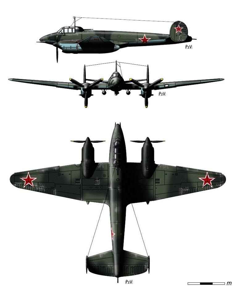
Wing span, m — of 17.13
Length, m — 12,67
Height, m — 3,93
Wing area, sq. m — 40,80
Weight of empty aircraft, kg — 5730
Take-off weight, kg 7860
Fuel, l — 2200
Engine type — 2ПД M-105R
Power, HP -2 x 1050
The maximum speed at the ground, km/h — 442
Maximum speed at altitude, km/h /535
Practical range, km -2150
Combat radius of action, km -1500
Practical ceiling, m -8600
The crew — 2 people
Armament: one 20-mm gun Svaki two 12.7-mm machine gun BK
Defensive armament: one 7.62-mm machine gun ShKAS
Bomb load: 2 x 250 kg under fuselage, 2×100 kg under the nacelles
ASSEMBLY INSTRUCTIONS
Before you begin assembling the model, You should choose the complexity of the build model: You can build a model with a transparent (open or closed) or an opaque canopy, or with retracted landing gear, moving or stationary elevators, the turn and the ailerons.
To work You need to prepare the workplace and tools:
1) clean the smooth surface (plastic plate or sheet of plexiglass);
2) cutting tools: scissors, cutter (can use a paper knife or a razor blade);
3) glue for paper (PVA glue), glue for the transparent parts (superglue, “globe”);
4) Shylo;
5) wire thickness 0.5-1.0 mm or toothpick (for the axis of rotation of the rudders and ailerons).
There are three main construction methods:
1. Assembly based on the “ship” frame, which is mainly used when building models of large dimensions.
2. Modular Assembly in which each section closes with the two sides of the frame, thus forming blocks. Ready-made blocks glued together to obtain a fuselage or other aircraft components. This requires careful adjustment of the two neighboring frames. For those who want to build a model this way you have two sets of frames.
3. The Assembly by gluing, which is described in this manual. Bonding is suitable for joining parts and sections are indicated by and double rooms.
PARTS LIST
1, 2, 3, 4, 5, 6, 7, 8, 9, 10, 11, 12 – fuselage section; 13 – inner part of the hatch of the cabin; 14
– the outer part of the hatch of the cabin; 15, 16 – lower the front part of the cockpit glazing; 17, 18, 19, 20, 21, 22 – the canopy; 23 – retractable ladder cockpit hatch; 24 – rim of the hatch; 25 – rim of the hatchway; 26, 27, 28, 29 – the steering wheel; 30 – axle of the wheel; 31L, 31P – elevators; 32L, 32R – plating stabilizer; 33, 34, 35 – spinner (2 PCs.); 36-battery; 37, 38 – pedal swing; 39, 40 – fairings cannon and machine guns; 41 – wall niches tail wheel; a 42 – seat pilot; 43 – the co-driver seat; 44, 45 -seat headrest of the pilot; 46, 47, 48, 49, 50, 51, 52, 53 – section of the nacelle; 54 -fairing junction of the wing and the nacelle; 55L, 55P – flaps wings; 56L, 56Р -skin wing panels; 57 – pedestal-seat pilot; 58L, 58Р – sheathing wing; 59L, 59Р – flaps of the wing; 60L, 60R – ailerons; 61 – fold chassis; 62 – fold Bay doors; 63 – traction of landing gear doors; 64, 65, 66, 67, 68, 69, 70 – chassis parts; 71 -inlets; 72 – cabin floor; 73 – cartridge boxes of machine guns BC; 74 – ammunition box cannon ShVAK; 75 – a box for shells of ShVAK cannon; 76 – a box of shells for the gun BK; 77
– hardpoints flap; 78, 79 – side of the instrument panel; 80 – dashboard; 81, 82, 83 – controls; 85, 86, 87, 88, 89, 90, 91 – details of machine gun ShKAS; 92, 93, 94, 95 parts gun BK; 96, 97, 98, 99, 100, 101 – details of ShVAK cannon; the 102 – gun belts, BK 103 cannon ShVAK tape; 104 – sheathing of the keels; 105 – wheels turn; 106-fairing stabilizer; 107L, 107Р-wing fairings; 108, 109 antenna; 110, 111 – detail of the pivot installation ShKAS; 112 – exhaust pipes of the engines; 113, 114 – channels water radiators; 115 – external hardpoints for bombs; 116, 117 nodes of the suspension of bombs in nacelles; 118, 119, 120, 121, 122, 123, 124, 125, 126, 127-the details of the bomb FAB-250; 128, 129, 130, 131, 132, 133, 134, 135, 136, 137 -the details of the bomb FAB-100; 138, 139, 140, 141, 142 – main wheels; 143, 144, 145 – the tail wheel; 146, 147, 148, 149, 150 – details strut tail wheel; 151, 152 is a screw; 153 is a ratchet; 154 – fold tail wheel; 155 – air intake oil cooler; 156 – cartridge drawer ShKAS; 157 spotlight; 158, 159 – parts of the output blinds water cooler; 160 – frame stiffness niches chassis; 161, 162 – spars of the wing center section; 163, 164 – spar wing panels; 165, 166, 167, 168, 169, 170 – the ribs of the wing, 171 – spars of the Elevator; 172, 173, 174, 175 – rib stabilizer; 176, 177, 178, 179 – rib elevators; 180, 181, 182 – skeleton of the keel; 183, 184, 185 – frame rudder; 186, 187, 188, 189 – the details of sight of the pilot: 190. 191 – housing of devices of the instrument panel; 192-fixing the machine gun ShKAS: 193. 194. 195. 196 – controls right side: A, D,
C, D, E, F, G, H, K, L, M – frames of the fuselage; N, O, P – frames and spinner; Q, R, S, T, U, V, W, X, Y frames of the nacelle. Z, Z1, Z2 – frames bombs.
The following items must be pasted on thick cardboard: 41, 72, 110, 111, 138 – 145, 160, 161, 162, 163, 164, 165, 166, 167, 168, 169, 170, 172, 173, 174, 175, 176, 177, 178, 179, 180, 181, 182, 183, 184, 185, A, D, C, D, E, F, G, H, K, L, M, N, O, P, Q, R, S, T, U, V, W, X, Y
The ASSEMBLY of the PROPELLERS (Fig.1)
To start gather with gluing spinner, don’t forget to paste the frames. Now cut parts of the screw; the blades should be given a convex shape, prokatov them along, for example, ballpoint pen. For rigidity possible along each blade to stick out. Ready screw attach to the frame, then screw with the frame insert in the fairing. If You want to make a rotating screw, in the center of each frame hole and into the holes: glue the axis of the wire or toothpick.
ASSEMBLY of the FUSELAGE AND the COCKPIT (Fig. 2, 3)
Assemble the fuselage to the details №1, 2, 3, 4, 5, 6, 7, 8, 9, 10, 11, 12, 13, 14, 15, 16 and frames A, b, D, E, F, G, H, K, L, M, N (the order of Assembly shown in Fig. 2). The fuselage can be divided into two parts: the nose – det. 1-7, 13, 14, 15, 16 (with the cockpit) – and tail – det. 8-12 (in section 8 is the tail wheel with a niche and a leaf tail wheel). Scheme of the Assembly of the cockpit and Assembly diagram of the growth of the niche wheels shown in Fig. 3. The details 15,16 cut “glass” and glue between the parts a transparent film. In the same way going the canopy (det. 17-22). In part 6 cut slits for the wing spars.
WING ASSEMBLY (Fig. 4, 5)
The wing model consists of a power frame (spars and ribs), skin, flaps and ailerons, as well as parts of the water radiator and landing lights. Designations: L – detail of the left wing R – right wing
Diagram of the frame shown in Fig. 4. In Fig. 5 shows how to assemble the frame, trim, radiators and headlight together. In detail, 46L, 46R, 58L, 58Р should make the slots for water radiators.
ASSEMBLY of the TAIL (figure 6)
The tail Assembly consists of a frame stabilizer spars (projections of the frames) and nervures; frame tail fins, stabilizer and plating of the keel, rudder height with ribs and rudder with ribs. It also includes the axis of the rudder (for right and left rudder) and the rudder. For the axles used straight segments of wire with a diameter of 0.5 mm. the Diagram of the Assembly of the tail shown in Fig. 6.
The ASSEMBLY of the NACELLE AND CHASSIS (Fig. 7, 8, 9)
On the model two engines, and hence two nacelles. Conditionally divide them into two parts: front (screw, engine compartment, exhaust pipes, oil coolers) and the rear (wheel well and bomb Bay doors). The General scheme of the Assembly and arrangement of parts of the nacelle shown in Fig. 7. If You build the model with landing gear, then use Fig. 8. Figure 9 shows how to assemble main wheels. The same is going and the tail wheel. Bomb Bay can be done with open doors and hang them inside the bomb. Parts of the right and left engine nacelles and undercarriage, not identified as L and R, suitable for both right and left side.
Assembling the BOMBS, CANNONS AND machine guns (Fig. 10, 11)
Guns should be collected before assembling the cockpit and fuselage. Their arrangement and Assembly diagram is shown in Fig. 10. The armament consists of 1 cannon ShVAK 20-mm (forward fuselage, bottom), 2 machine guns BC 12.7-mm (in bow) and 1 machine gun ShKAS 7.62-mm (in the cockpit of the Navigator-arrow). Bomb armament of the aircraft consists of two bombs FAB-250 under the wings of the aircraft and two bombs FAB-100 in the bomb Bay of the nacelle.
The materials to build a model FIGHTER PE-3 (download)
Recommend to read
 “SNOWFLAKE” WITH MOTOR
Any Amateur ice-fishing dreams about the convenient and easy means of transport to quickly get to the coveted perch holes? In one of the rooms "Modeller-designer" I read about motorware...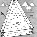 THE METHOD OF EXCAVATION…
The British magazine "Practical Householder" reminds readers about the DS one the oldest methods-plan sections using the so-called Egyptian triangle with sides in the ratio 3:4:5. If you...
