 His appearance in the editorial was met with a, frankly, no enthusiasm; preliminary telephone conversation were no signs, it seemed, nothing sverhinteresnogo. Homemade paper? Well, someone today, they will be able to inspire! It’s long passed stage — paper model…
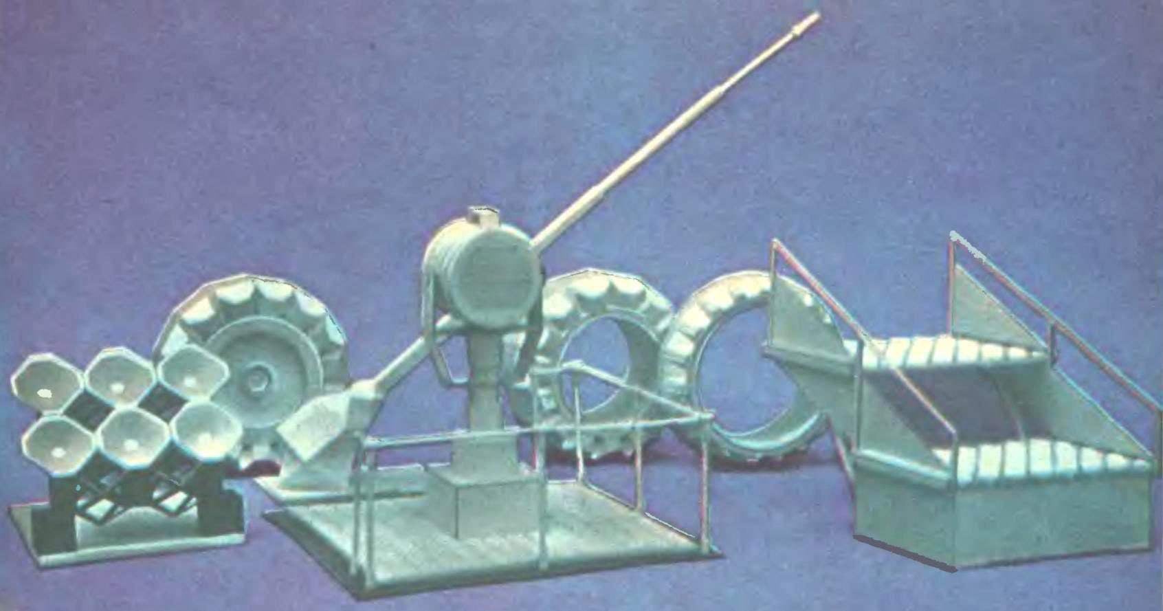
But the chair hoisted a cardboard box and from it one after another on light there are very interesting models of cars, wheels with raised tread pattern, model ship spotlights, masterfully executed decorative cladding panels. I had the impression that all these “toys” made of plaster. And almost absolute weightlessness testified before us on paper.
Yes, I used that sheet of paper is a plane, and transform it into a volume only in the form of simple shapes — cubes, cylinders, prisms, tetrahedra, pyramids. But that showed us author and teacher of the Oryol pedagogical Institute Anatoly Serafimovich Bliznyuk, rejected formulaic ideas. Simple geometric shapes flow into each other, emphasizing one face, obscuring another, and so form a complex surface that is simply impossible to believe in their “planar” nature.
Department of drawing and labor Orlowski Institute has long been practicing geometric modeling of paper in the learning process. What is the difference of this method from the method of vyklevyvanija conventional paper toy pattern?
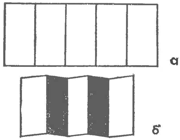
Fig. 1. Transformation worksheet with a grid of parallel cuts in the workpiece:
a — marking of paper b — “accordion”
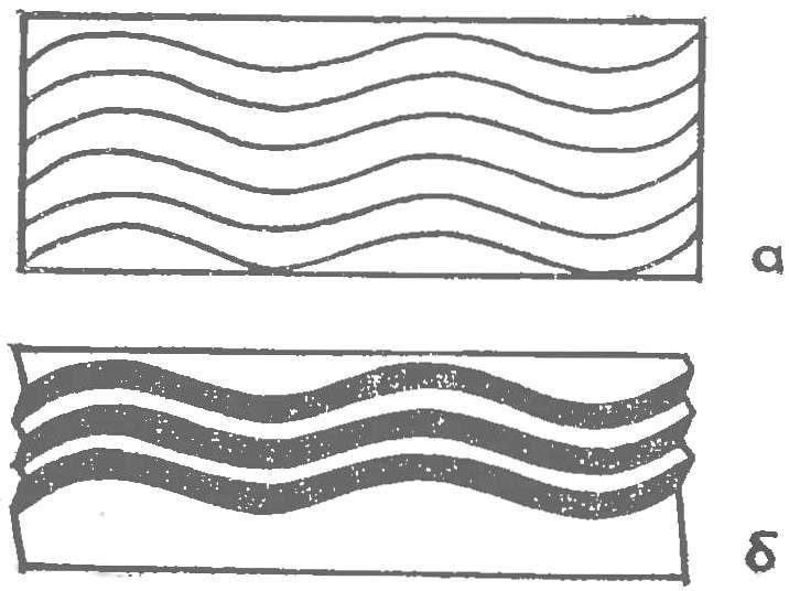
Fig. 2. Obtaining a volume using a grid of sinusoidal cuts:
a — layout, b — obtained by means of the relief
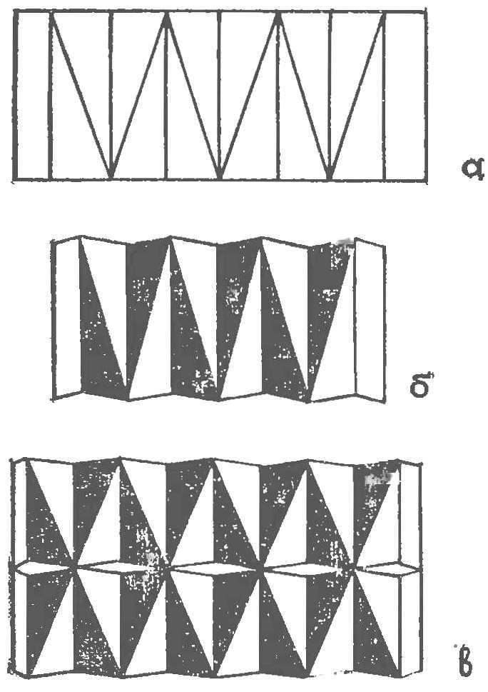
Fig. 3. Education simplest relief:
a — layout, b — folding, V — version sticker on the panel
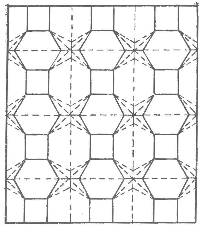
Fig. 4. The construction of complex surfaces
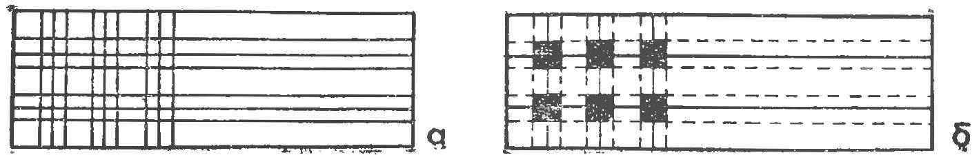
Fig. 5. The layout of blanks for the manufacture of caterpillar tracks:
a partitioning scheme, b — the cut
First, when gluing, do not apply the so-called valves, that is, angled shelves, which incorporate elements of the scan; gluing is conducted back to back, it gives a very clean face, almost not differing from the bent.
Second, the used method of pre-notching the future faces of terrain: the paper easily and without distortion bent. The blank is incised from the front surface and the back of it, clearly formed in the intended shape.
In-the third, and perhaps most importantly: the method used by A. S. Bliznyuk, truly universal. It can be used to transform the plane of the sheet in any, arbitrarily complex surfaces. If we talk about the future, this technique is easy enough algorithmsuite, that is almost always possible to make the program run terrain.
We believe his story about the new features of the paper will be interesting for heads of clubs initial modeling and model designers with a passion for making a desktop models. Many will find it useful, and readers interested in pure home designing — interior decoration, making lamps, etc.
Paper… We are so used to it, or rather, to the fact that the sheet of paper is almost a mathematical plane, to see the volume which can be obtained from it, will always fail. Meanwhile, the paper — very interesting material for model making or a desktop publisher. Introduction to design paper elements allows to facilitate the model, preserving at the same time its strength and rigidity. Even details such as Reiki, pieces of wood or plywood can be replaced with curved accordingly flipcharts.
The paper has sufficient tensile strength, kink and abrasion and also well-glued almost any glue and beautifully painted.
The instrument will require the simplest. For marking — ruler, meter and a compass, and for all sorts of cuts, cut — a scalpel, a penknife or safety razor blade.
For a start some exercise. Material — drawing paper, instrument, metal ruler and scalpel.
Put a ruler on the sheet and try to make it to the cut about half the thickness of the paper blank. You will, of course, not immediately. But after a few cuts you will feel, what should be the force applied to the cutting tool to make an incision of the required depth.
Eating and this operation will cause trouble, we recommend you at first to penetrate the paper through, and then gradually decreasing the pressure on the knife to get the clear cut half the thickness of the sheet.
The main element that later you will meet constantly, is dihedral angle. It can be obtained by bending the workpiece along the cut line, the edge will be perfectly straight.
And now try to do one incision, and four, fulfilling the following condition: odd lines cut into the front side and even inside. If you then bend the notched elements, that formed some semblance of an accordion (Fig. 1A, b). Now several complicate the task — we need to perform incisions in the form of a sine wave. Repeating the already described operation, will receive a surface with a topography (Fig. 2A, b).
We should not think that these examples all and limited. Based on the markup of any rhythmic series and to vary accordingly the partitioning step, you can get a variety of reliefs.
If we partition the surface of the sheet geometric shapes, for example triangles (Fig. 3,a) and notching the odd parallel lines on the front side, and even from the inside, after the paper limb elements we are raised workpiece. Several such blanks, glued to a piece of cardboard, you can assemble a decorative panel with a very interesting pattern (Fig. 36).
Now, when some of the basic techniques of working with paper you mastered, move on to more complicated surfaces. Mark the paper sheet as shown in figure 4. At a cut note that the solid lines incised on the front side, and dashed inside. To facilitate his work, turn to the back side of the sheet with a needle the point of intersection of the dashed lines. It is already possible to do without re-marking, directly on the line connecting the point of punctures. Further, putting a sheet on the table, gradually move the paper from the edges to the center, while the outer notches become convex edges of the relief, and the inner — hollows.
We have considered only examples of the relief formation from a flat sheet of paper, not bound in common with real technical objects. However, if you prefer, you can play almost any element of almost any layout. Show, for example, the method of constructing the caterpillar drive of the tractor or tank.
Take a sheet of heavy paper with dimensions of mm. 55X500 markup will choose two main loops 15 and 5 mm and applied to the blank grid-lines; the distance between them must conform to the schema (Fig. 5) 15, 5, 5; 15, B, 5, 15— in width and length. As in the previous case, with the front of the scalpel are the solid lines, with a back — bar. If, say, we have to work with repetitive markup, there is no need to draw all the lines, it is enough to portray the three or four recurring item, and then using a needle to consistently carry them for most of the paper blank.
Finally, after completing the graphical part of the work and scoring can proceed to the next operation. It’s called “cutout”. Shown in figure 56 the contours of the cutouts are highlighted in black. It remains to bend the elements in the notched places, and the flat blank transformirovalsya in embossed tape, like the track of a tank or tractor.
Another method of shaping is the use of standardized elements — distinctive building blocks from which you can build different layouts and models.
First, a little theory. In geometry there are so-called Platonic and Archimedian body filler. Their characteristic feature — the common docking area, with which such bodies can be arbitrarily articulated.
It turns out countless options, allowing different combinations of shapes.
Since most of the layout is performed by the method of expansions, let us dwell on the methods of their construction and replication. To illustrate, consider the unfolding of the cube. Prepare the meter, a compass, a pencil and two colored red and blue, graph paper, drawing paper, regular school ruler and a cutter.
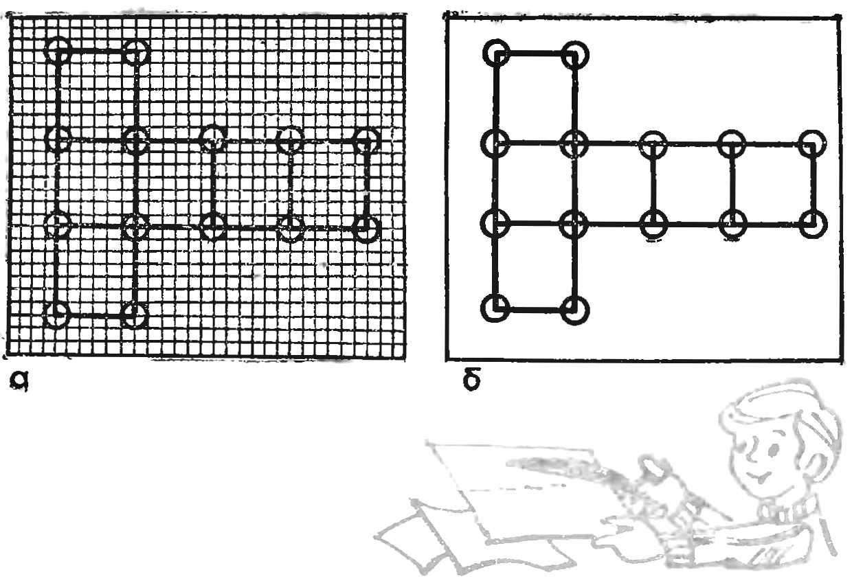
Fig. 6. Build sweep Cuba:
a — on graph paper, b — on the paper
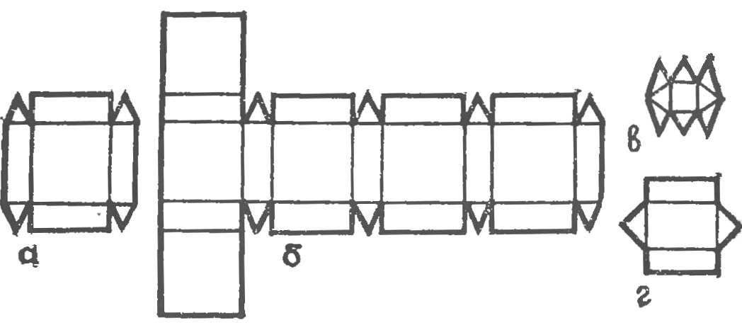
Fig. 7. Building dvadtsatishestiletnego — cube with truncated edges:
a — building the recurring item scan, b — scan complete, in — building sweep of a triangular prism, g — scan of the body which mates with the first two.
Fig. 8. Scan a series of polyhedrons designed for vyklevyvanija searchlight installation:
a — recurring item, b — scan quadrangular prisms, in — scan of the cube octahedron.
Fig. 9. Scan a series of polyhedrons (for vyklevyvanija pipeline):
a — scan element dvadtsatishestiletnego b— scan of the connecting zone,, g — scan direct octagonal prism.
You should start with marking the pattern on graph paper (Fig. 6A). Characteristic points of the sweep in this case are enclosed in circles. Then graph paper is superimposed on the sheet of drawing paper, and these points perekalivatsja him. The perforations on the paper are also marked by circles (Fig. 6b) — this way you won’t lose them on a sheet of paper. In accordance With the pattern of points on the line are connected by thin lines ostrozatochennym pencil.
To further avoid confusion, we introduce the legend for the various lines: line cuts (face) we draw a simple pencil, sections in red, and the cuts from the inside blue. Carefully drawn billet is the original from which perekryvaniem needle to obtain the necessary number of copies.
The sequence of operations is the gradual transition from the sweep to the polyhedron from the polyhedron to the combination, that is, the construction of spatial shapes on the basis of shaped bulk bodies.
Let’s try to understand the following example. Build a spatial scan of the body, resembling a cube with truncated edges. It scan consists of six squares, twelve rectangles, and eight scalene triangles. Draw on graph paper the square, and then on each of its sides construct a rectangle, large side being the side of the square and the smaller one is selected arbitrarily. On the smaller side of the rectangle constructed versatile triangle — scan (Fig. 7a, b). It remains only to percolate it on a sheet of drawing paper, make appropriate cuts and glue the blank into dvadtsatishestiletnego.
We considered all structural forms have common elements-a plane, with which they can be connected with each other. The result of a game is the combination of polyhedra — you can get many different shapes.
The tab shows a photograph of a train of containers, standing on the platform. The container in this layout is nothing like our cube with truncated edges.
Build a three dimensional body. The first polyhedron must contain six square and twelve rectangular n eight faces are equilateral triangles. The body is a recurring element shown in figure 8A. To build an arbitrarily selected side of the Central square, is attached to each of its sides on the rectangle, and to the two large sides of the rectangle for docking of an equilateral triangle with sides equal to the larger side of the rectangle. We have already pointed out that there is no need to perform the drawing of the entire sweep is enough to portray a recurring element, and further construction done by multiple perekryvaniya on Whatman main recurring item.
The second polyhedron, which we need to build is a right rectangular prism with two bases-squares and four rectangular faces (Fig. 8b).
And the third star of this series (Fig. 8b) is a cube octahedron, OI consists of six square and eight triangular faces. The Windows, shown in the drawing, is designed to ensure that the layout was perceived as consisting solely of edges.
With the last three bodies can play a very interesting design, such as the model of a searchlight installation (photo tab).
And finally, the last series of polyhedra. They are useful in modeling the fragment pipeline (see box).
The first is dvadtsatishestiletnego — consists of six octagonal wrong, wrong eight hexagonal and twelve square faces. The dimensions of the sides faceted selected at random. Scan this multifaceted cell is shown in figure 9a. For full figures need to prepare two such sweep (top and bottom), connecting the zone between them is shown in figure 96, it consists of four rectangles and four irregular octagons.
It remains to portray the sweep of two straight prisms with octagonal bases (Fig. 9b and d) and correlation with the picture on the tab, the model is applied to the wall of the pipeline or other similar device.
A little about the technique of gluing. For sufficiently accurate execution of gluing it is possible to produce butt joints, adhesive bonding in this case is quite durable and reliable. The novice desktop publisher at first, we recommend to glue the elements sweeps through valves. They are, however, somewhat detracts from the appearance of the layout, but with them you can get a pretty decent joints.
A. BLIZNYUK
Recommend to read
 AMPHIBIAN XXI CENTURY
In late September 1998 in Irkutsk, an event occurred that had no publicity, but, nevertheless, its significance is far beyond the scope of this Siberian city. From the airfield of the... VALVE FROM THE FLOOD
There are cases of disconnection of water in homes for a long time not only for repair of water system, but also for its economy. Such breaks is fraught with the danger of flooding the...
