ASSISTANT WELDING

WELDING ASSISTANTThank you so much, friend magazine, for the development of welding transformers. Inspired by the publications took a chance and made themselves compact, but quite powerful “svarochnik” based on “on the margins” of the burnt stator from a induction motor. Now that dream is about as good design of the rectifier… help me out, dear journal. On you one hope!

 
L. Bornovolokov,
Kemerovo

In an editorial post, this is not the only request for material of rectifiers for small-sized welding transformers. Hence, such development is really needed rather wide circle of readers. They addressed the following material.
 
Designed and improved homemade welding machines on the basis of the toroidal magnetic circuit is engaged not the first year. But when the editors of such a respected among the fans of DIY magazine as “modelist-Konstruktor”, offered to tell about the most successful developments, several podrasteryal. And discriminating readers have ventured to submit only two compact welding rectifier.
 
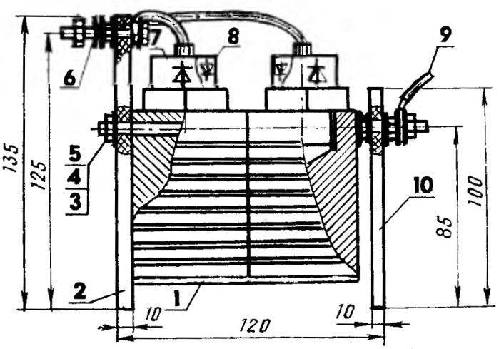
The first is combined with a toroidal transformer and fan-cooled. Directly the rectifier bridge, assembled on the diodes DL-132-80-10 installed in the center of the Torah in brackets-the radiators from pieces of aluminum angle. Thermal conditions for power semiconductor valves is the most favorable. After all, each of the diodes from almost all sides by air at the kom, which are sucked from the bottom (from under the stands) and intensively chased by a fan through the “mini wind tunnel” — the inner funnel (window) Torah.
However, for such a free “blowing” had to worry about the optimality of the layout of the unit. In particular, to provide that holes of relatively large diameter was at the base and tightening the lid, which is attached (through the flange) three phase multiblade fan of UVO-2,6-6,5-U4. And that the air intake was also from the bottom without interference, the height of the screw to the base of the footings should be at least 20 mm.
 
Now a few words about the peculiarities of the connections of the diode bridge to the output transformer. With heavy use of the apparatus for welding one of the terminals of the diode bridge is connected to the common terminal, and the other, as in this case, “floating” docks with a particular output transformer. If the required voltage of 6 V, 12 V, 18 a, etc., both input diode bridge are made transient (floating).
 
Welding machine DC
 
Welding machine DC:
 
1 — stand (wood, plywood, s20, 4 PCs.), 2 — base (plywood, s10), 3 — screw with countersunk head (8 PCs.), 4 pin (4x), 5 — tip terminal (4 pieces), 6 — stud M6 (bronze or brass, 4-piece), 7 — nut M6 (bronze or brass, 16 PCs.), 8 — washer (bronze or brass, 20 PCs.) 9 — nut-lamb M6 (bronze or brass, 4-piece), 10 —handle swivel-hinged (from a scrapped radio, 2 PCs), 11 — fan Grechany SVR-2,6-6,5-Y4 (in a round case with a phase-shifting capacitor 2 µf) 12 — M4 screw with washer Grover (3 piece), 13 — coupling cap with a Central hole for the fan (plywood, s10), 14 — core toroid (stator of the asynchronous motor), 15 is the primary winding of the transformer (number of turns, bends, wire diameter is calculated), 16 — layers of insulation (thickness and amount of settlement), 17 — gasket ring (electrotechnical cardboard, s 1 …2,5, 2 PCs.), 18 — insulation outer (winding lactinol ribbon in 1 — 2 layers), 19 — a bracket (aluminium angle 75×50, 2 pieces), 20 —diode FOR semiconductor-132-80-10 (4 PCs), 21 — the Central bracket (aluminum bracket 60×60), 22 — screw pan head (6 PCs.); D1 and D2 — dimensions of the fan.
 
Rectifier

 
Straightener “Baby” for the “svarochnik”:
 
1 — heatsink diode (4 pieces, tied in pairs), 2 — bar network (textolite, plywood, s10), 3 — pin M8 (bronze or brass, 4 holes) 4 — M8 nut (bronze or brass, 18 PCs), 5 — washer (bronze or brass, 28 pieces) 6 — M8 screws terminal (bronze or brass, 2 PCs.), 7 — diode rectifier B200 powerful (2 piece), 8 —diode rectifier a powerful ВЛ200 (2 PCs.) 9 — conclusion from the rectifier to the load (2 pieces), 10 — rectifier panel (plywood, s10), 11 — strip the insulation (rubber Velocimetry); a) is a schematic diagram of a rectifier bridge.

 
The rectifier allows to improve the ignition of the arc due to the increased open circuit voltage, and improve the quality of welding. In addition, we must not forget that the plus output generates more heat. And the property is, as they say, a sin not to use when welding thin-walled parts (here “+” is applied to the electrode).
Now, on to my second design. This is a standalone rectifier (it can be used with virtually any device at a current of 200 A). With a simple wiring diagram diode bridge primitive standard, the design actually will not name. The singularity of it is to use two groups of bipolar diodes — B200 and ВЛ200 (the external difference between them, respectively, green and crimson body). So there is a real opportunity to connect the radiator of the diodes in each of the groups. That is in the same group on the radiator turns on “+”, another with “—”. Homogeneous connected with pins M8, and between diverse installed rubber gasket. The whole construction turns out very compact and reliable.
 
Another feature here is obvious: the conclusions of the diodes can be used as handles for carrying the rectifier. The more that the weight of all the devices does not exceed 5 kg.
 
O. VLADIMIROV

Recommend to read

  • THREAD INSTEAD OF TAPETHREAD INSTEAD OF TAPE
    No, the Council is not for Amateurs. Although for them, too, because everybody who is going on the road, among other things, I'll try not to forget the needle and thread may come in...
  • “EAGLE” THE FIRST-BORN RUSSIAN FLEET“EAGLE” THE FIRST-BORN RUSSIAN FLEET
    Will have to make a reservation at once — reliable information, which is not causing doubts and questions about the shape and design of the firstborn of the Russian Navy, very little....