 The proposed device is designed for “soft” on various radio and electrical household AC voltage of 220 V it is Known that the moment of switching devices containing a primary or secondary power circuits the capacitors of large capacity (high power audio amplifiers, switching power supplies and other devices), accompanied by a cast of current, which can reach tens of amperes.
This current not only corrupts the elements of switching (quickly wear out mechanical contacts), and creates a strong disturbance in the power supply, but may also damage the diodes of the rectifier or power transformer in addition to the protection of radio equipment, the proposed device can be used to limit the starting current commutator motor or for the protection of a powerful halogen (photosplitting) lamps in constant use recommended devices enables energy savings of hundreds of kW (depending on power load), which is an important incentive for the application of the Electric circuit device is shown in Fig.
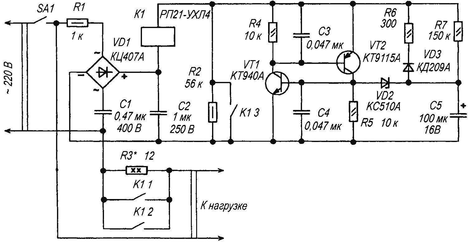
A circuit diagram of a device limiting the starting current
As part of limiting the starting current, powerful wirewound resistor R3 At the time of the supply voltage the relay contacts K1 are open and the voltage across the load flows through the resistor R3. Simultaneously rectified by a diode bridge VD1 voltage is supplied to the node control relay, whose task is to create the necessary delay of the relay closure. The capacitor C2 smooths the ripple of the rectified voltage. The delay time is determined by the circuit parameters R7, C5 as soon As the voltage on the capacitor C5 exceeds 10..12 V, the Zener diode VD2 opens, followed by open high voltage avalanche transistors VT1, VT2, forming an analogue of the SCR with a low current control Transistors include relay K1. Capacitors C3, C4 prevent premature opening of the transistor due to noise. Circuit R6, VD3 is designed for quick discharge of the capacitor C5 after the opening of the transistors of the Group of relay contacts K1 3 provides the willingness of node delays, if the time between successive switching on / off ЅА1 is less than 0.5 minutes. External view of the device shown in the photo.
Details
Resistor R3 is a wire, the resistance and capacity of which are selected based on the type of the protected device. It can be composed of several resistors PEV-10, or made of a thick high impedance wire. The remaining resistors type MLT, S1-4, S2-33 corresponding to the power Capacitors C1, C2 — K73-17, K73-39 (C2 may be oxide), C3, C4 KM-5, K10-17, Instead of the transistor VT1 can be used КТ940АМ, КТ969А, КТ9179А, МЈЕ340, 2ЅС2330, VT2 — КТ9178А, МЈЕ350, 2ЅА1625. The diode bridge VD1 is replaced by any low-power for a voltage of less than 300, or 4 diodes, for example, КД102Б, КД105Г, КД221В, 1N4004 Zener diode VD2 can be any low-power on 9. 13 (Д814Г, КС221Ж, КС508А) Relay K1 — the most crucial element in the device, the choice of which should be treated thoroughly In this design used a relay РП21-NF4 (GOST 17523-85) three groups of contacts and a coil resistance of 6 ohms Without making any changes to the schema, you can use the same relay RPU-O-NF4 with a coil resistance of 5 ohms is Also good will work more sensitive relay RPU-2УЗБ with a coil resistance of 13 ohms using the latest damping capacitor C1 can be a lower capacity In this device limiting the starting current of the popular relay RES-9, RES-22 and similar electrical characteristics At specified in the diagram the values of R7 and C5 delay relay operation is 1.5 seconds To operate the device to load with high-power pulsed power supply (or to soft start most motors) enough of a delay circuit of 0.5 s. .1 If the protected machine uses a conventional power transformer, then the delay can be increased to 2..5 C During operation of the current limiter in conjunction with the amplifier AF, which has a smoothing capacitors with a total capacity of 80,000 µf and a power transformer with a primary winding 1 resistance 2 Ω, when specified (in the diagram) the nominal value R3, the initial inrush current decreases from 55 A to 13 A, which ensures a soft start of the machine. For the protection of powerful lamps from burning out when you turn instead of the resistor R3 can deliver a powerful diode, for example series Д246…Д248. If you want to be soft on the load capacity of more than 2 kW, the contacts of the relay K1 needs to control a magnetic starter with a higher load capacity.
A. KASHKAROV
Recommend to read
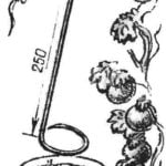 “THE HOOK” FOR TOMATOES
Tomatoes and cucumbers for pickling or marinade is usually rolled into a three-liter jar. I'm gonna put it just, but then how to get it? The cucumbers are slipping, and red bulk tomatoes...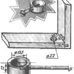 NUT-RING
In commercially available furniture are widely used the connection of the horizontal parts from the vertical in the furniture bolts and nuts curved shape. located in special recesses. In...
