This mode can be selected by switch S2. As soon as the account reaches the “prohibited” 7 or 21 points via R11 to the input of the cascade on the VT3 enters the log. 0. The signal is inverted and fed to the reset input of the counter. In addition to the logic functions cascade on the VT3 performs another function. The fact that one of the problems when working together CMOS and TTL circuits is not sufficiently high voltage is logical 1 last. Here it is amplified to almost the supply voltage. The logics of this node there is another feature: in the accepted system of decoding the number 21 is “mirrored” by the number 5, which can lead to premature reset of the counter. Therefore, a 20-sided mode on VT3 through R10 is served inverted fifth level of the counter. Because of this, when the numbers that are less than 16, the transistor opens and the reset input, the counter will log.0. regardless of other signals. During starting (when the button is pressed S1) LEDs of the selected range are highlighted slightly by current pulses, “running” on them That allows you to verify the health of the scheme and all of the LEDs.
When using the dual-mode e-cube, the following error is possible, work in a 6-sided mode when you need a 20-sided. The result may be that powerful ballista categorically refuse to penetrate the armor of the Marines. Therefore, the required effective display 6-sided mode. No tricks with digital indicators can not eliminate the error absentmindedly. In the proposed design display 6-sided mode led HL7, which is his kind of visual limitation included range of reference. Not to notice that instead of one of the desired burn from two LEDs, is impossible, and OTO — another advantage of the adopted positional display system. Not to short-circuit to earth will. 7D3, it is separated from the switch by a diode.
A circuit diagram of a combined “6-sided” and “20-sided” electronic “dice” for games
Topology of the printed circuit Board
Voltage regulator 5V (chip DА1) mounted directly on the Board. Because of this, to supply the device, you can use practically any network adapters with an output voltage in the range 9 — 12V, the benefit of consumption current does not exceed 80mA. Acceptable option — 2 — 3 battery 336 which are connected in series. But in this case the design will need to enter the power switch.
About the parts: transistors VT1, VT2 can be any of series KT361, КТ203, VT3 blocking — n-p-n structure, KT315 series, КТ301, КТ312. Chip К176ЛА7 interchangeable on K561LA7. D3 — 155 or 1533-series. Such changes do not require changes to the wiring circuit Board. Only К1533ИДЗ may be in a more narrow case, but the Pinout is the same.
However, it may be that the acquisition of the needed chips will be difficult. Almost all sold now in stores “logic” — 1988 — 1992 release, and these stocks are low. It remains to replace the chip to other, similar purpose. So, as the D2 you can use the chip К176ИЕ1 — simple 6-bit binary counter. As a D1 — a chip with three elements. In this case, the element D1.2 is eliminated, the signal of the start to one of the inputs D1.3. The Application Of D1.2 is good because it still produces pulses of the multivibrator. But the counters will work in this shortened version of the schema.
Remind about need of observance of rules concerning mounting of semiconductor devices: CMOS chips should be stored wrapped in foil, low voltage soldering iron with a grounded tip. This is especially true of circuits in early development, when designers were reluctant to install protection elements due to the lower performance In applications of solder or something suspicious chips use the socket. LEDs, particularly in a plastic housing, soldering should not be closer than 10 mm from the body, preferably using an additional heat sink.
Switch S2 – any three sets of changeover contacts. In the present device applied П2К 2 buttons with dependent fixing. It contacts the pins on one side are shortened. Button S1 — type KM 1-1, or the like. The selection of colors of LEDs (for example, the first 6 of a different color), readers can make at its discretion. Capacitors C3, C4 — ceramic of any suitable dimensions.
Design. Since the device has not been used super technologies like photolithography and plating holes to plant all the conductors of the printed circuit has failed, the Remaining compounds 3 and 4 level arrangement of the mounting wire (preferred MGTF). On sharp the tweezers is formed by a ring and worn on the output of the chip. It remains only to touch it with a soldering iron. Similarly, most of the wires to the LEDs are soldered directly to terminals D3, moreover, the indicators in the device are the part of the foil.
DА1 bolted to the radiator of a small aluminum plate. In the opposite case it is desirable to make the vent holes. As for the housing and front panel of the electronic “dice”, they are made of boxes, cut out the back plastic wall of the old TV.
Layout a detailed schematic of the electronic “dice” and the housing
The Board is located down the details and is attached to the body using a rectangular pillar and two M3 bolts with countersunk heads. This rack, as it mounts S2, it is better to make polystyrene that will allow you to glue them to the hull. Then to the Board two nuts screwed on metal bracket with button S1. The button is located so that pressing on the body it works.
Inspect bays solder and short circuits between tracks. Check the polarity of all the LEDs. Correctly mounted from serviceable parts the device does not require networking. The final verification of the correct Assembly and functioning of the device can be done very effectively: connect in parallel the capacitor C1 with a capacity of about 0.33 UF. Press S1 If everything is assembled correctly. you can watch the beautiful effect of the running lights in the range, selected by switch S2.
Front panel of the unit painted gold enamel metallic paint in bronze and is styled with ancient Greek shield goplon.
So help you Pallas Athena (the Greek mythical goddess of war and victory, as well as of wisdom, knowledge, arts and crafts) in the technical work and fight!
A. LISOV. Ivanovo
Recommend to read SAWMILL-IMPROMPTU Lumber for construction in the suburban area is always a concern and sometimes a problem. At the same time when clearing dedicated to building playgrounds felled trees — not such a... ON TOP BEFORE THE FALL A clear success with the development of missile cruisers of the "terrible", in fact, the rocket ships of a new type, clearly required further development. However, before the... 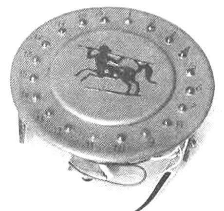
 There are many games in which, for example, the number of points scored by the player. is determined by throwing dice. It is easy to make and the electronic “dice” random number generator. Schemes of such generators and descriptions found in Amateur radio literature.