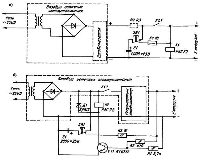
Consider a circuit protection circuit, which can be successfully used in battery chargers and power supplies unregulated voltage (Fig. a). By pressing the SB1 button the relay K1, which switches to the hold-in, hold in closed condition, the contacts K1.1 and summing the power directly to the load. If you experience the same short circuit in the power supply output voltage sharply decreases, the relay coil is de-energized, which causes contacts to open and disconnect the load from the source.
Re-enabling the load button SB1 is possible only after elimination of the fault. The capacitor C1 is charged to the output voltage of the power source is discharged to the relay coil, causing the K1 to work. Resistor R1 limits the current pulse discharge, preventing destruction of the internal structure C1 in case of erroneous inclusion of a load when a short-circuit at the output of the power supply has not yet been resolved. Resistor R2 limits the short circuit current of the rectifier diodes. It can not even enter in this scheme, if diodes are designed for pulses exceeding the amplitude of the short-circuit current. Otherwise referred to as the resistor required. Remember, however, that the output voltage source in this embodiment should be greater than the voltage drop across R2 at the rated charging current or load current.
Relay protection of power supply against short circuits with a fixed (a) adjustable (6) voltage output
AVM protects against overcurrent, relay protection which is not available. Circuit breaker (or switch multiple, automatically recoverable) is installed instead of resistor R2, since the resistance of the AVM usually not much greater than 0.4 Ohm.
Now consider a circuit protection circuit, which can be used in the power supply with adjustable output voltage (Fig. b). As the previous, the load is activated the button SB1, pressed, capacitor C1 is connected (through resistors R2 and R3) to the base of transistor VT1. If there is no short circuit, VT1 opens, having the necessary bias voltage. Work relay K1, turning on your contacts K1.1 and adjustable base stabiliser and the load. Now the output voltage, whatever it is, will be to support the VT1 is in an open state.
Well, in the event of a short circuit on the output base of the transistor will be grounded through the resistor R2, and e-guardian — a semiconductor triode closes almost instantly. As a result of this operation will takes out relay K1, turning off the stabilizer, and the load.
The role of the resistor R3 in the second scheme is similar to the purpose of R1 in the first scheme. The capacitor C1 during operation of the stabilizer performs the function of the capacitance of low frequency filter. The VD1 diode protects the transistor VT1 from the induced current that occurs when switching the relay coil K1.
The parameters of the relay depends on the rated current of the charger or power supply. For example, charging a car accumulation you must choose a relay rated voltage 12 V with maximum current capacity of the wiring 20 (or more). Such conditions are satisfied, in particular, РЭН34 (passport ХП4.500.030-01), closing the contacts which you want to enable in parallel. You can also use 12-volt relays with divorce contacts at least 3 mm and a nominal current of 20 A and more.
It is acceptable for chargers and power supplies with rated current up to 1 A and the relay RES22 (passport RF4.523.023-05) or similar current switching and operating voltage. The capacitor C1 in both schemes, the oxide, the number K50-12, K50-16 and similar types. As resistors s — LANG fit common MLT-0,5 or MLT-0,125. The only exception is high-current (32 (Fig. a), it must be a wire. Transistor /T1 — КТ815А, КТ817Аили similar semiconductor triode of medium power. Wide scope for choice has ЛЭ1, which with the same success working diodes КД410, KD503, KD512, КД519, KD521. Button БВ1 — of any type.
With good detail and correct execution of the installation performance of both schemes is provided, as they say, a hundred percent.
D. ATAEV, Sterlitamak, Bashkortostan
Recommend to read
 APPLES CLEANS… HARVESTER!
As practice shows, to grow crops — not all. It is much harder to remove, and then save it. Fully all that relates to the collection of apples, pears, peaches and other large fruit. Are... THE SQUADRON BRONENOSEC SEVASTOPOL
THE SQUADRON BRONENOSEC SEVASTOPOL. Scale model 1:200. A plan to strengthen the Baltic fleet in 1891-1895 he was provided, among others, the construction of five armored ships...