
 We offer a simple pocket radio with low voltage power from the supercapacitor. The receiver is fully on transistors, because the low voltage does not allow to use the existing chips (e.g., 174ХА10). Receiver of direct amplification, which provides sufficient volume to broadcast stations in the medium waveband and working in a range of supply voltages from 2 to 0.9 V.
As a power source to use a 1.5-volt battery. When working on a speaker of the current mode signal is around 10 mA, stereorelease (2×35 Ohm) — not more than 3 mA When charging the supercapacitor to 2 V receiver works on the phone about 10 hours, and the speaker — about 2.5 hours to discharge it to 0.9 V.
Before proceeding to the direct description of the scheme and work readers of the receiver, I would like a few words to devote to the supercapacitors, the use of which this product is one of the important points.
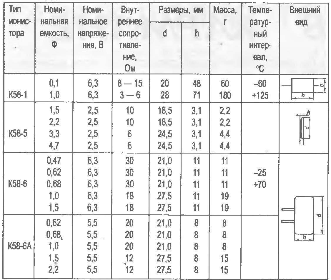
The device of the supercapacitors, the story of their creation is widely discussed in our technical literature. I would like to draw readers ‘ attention to the work of N. Kochetova “Supercapacitors” published in No. 2 of 2001 of the journal “modelist-Konstruktor”. Along with the description of principles of operation and construction the article provides information about the most common at that period the domestic production of supercapacitors goo “Helion” from Ryazan. Currently, the range of these products greatly expanded, including the products of JSC “NII GIRIKOND from St. Petersburg (see table). A fairly complete review of the practical application of supercapacitors and their characteristics are presented in the work of I. Aliyev and S. Kalganova “Capacitors ultra high intensity or molecular capacitors” — Reference book, Moscow, 2005
One of the remarkable properties of supercapacitors is their quick charge: in just a few minutes, instead of hours as with a standard battery. For example, for a 100-paradnogo of the supercapacitor 2 minutes. And not have to deal with acids, alkalies, distilled water, hydrometer. There is no concern about venting the charging station: still a hazardous industry.
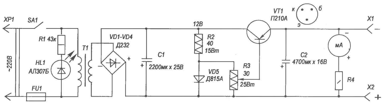
Figure 1 shows the author developed the circuit diagram of the charger of supercapacitors for powering handheld radios. Such a device must withstand when connecting a strong inrush current, so the proposed scheme is applied high current electronics. Rectifier bridge — diode Д232, transistor — П210А, Zener — Д815А. Transformer capacity of 50 watts. The value of R4 is not specified, since it is directly related to the applied electrical measuring instruments. In the proposed design used a moving coil milliammeter М4202 with the current full deflection of 5 mA and a resistor of 1 K

Fig. 1. A circuit diagram of a charger for an electric double layer capacitor
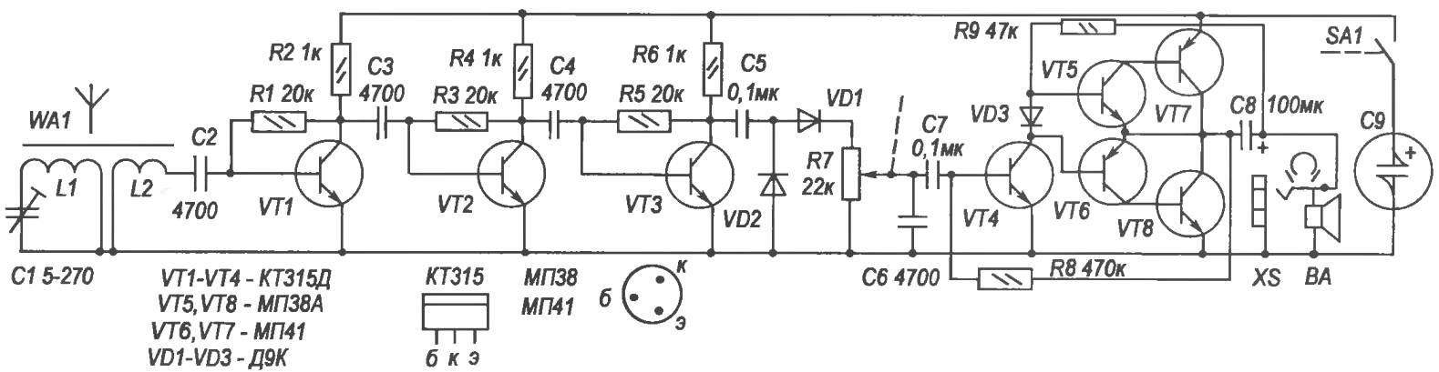
Fig. 2. A circuit diagram of a pocket radio with a low supply voltage from the supercapacitor
Now, refreshing your knowledge about supercapacitors and positioning the charger to it, turn our attention to the aforementioned pocket receiver. Its schematic circuit diagram is presented in figure 2. The reception is on a magnetic WА1 antenna consisting of antenna coil L1 and coil L2 when placed on a ferrite core with permeability of 400 marks 160 length and 8 mm in diameter. Both coils are wound the wire PMTL-2 with a diameter of 0.18 mm. And has 75 turns, the inductance of 340 µh ±10%, 1.2— 7 turns. This antenna and adjusted the capacitor C1 is taken from the radio receiver “Selga 404” (use one section of double block variable capacitors). With the coil L2 when the signal arrives at the input of three-stage amplifier high frequency (UHF). Each cascade UHF, performed on the transistors VT1 — VT3 blocking imposed negative feedback voltage connect the base resistors R1, R3, R5 to the collectors of the transistors. Off load the last of the cascade UHF resistor R6 through the capacitor C5 of the signal supplied to the detector cascade according to the scheme of doubling the diodes VD1, VD2.
A capacitor C6 is used to filter the high frequency component of the signal. With the exit of the detector cascade the signal to the volume control R7 is coupled with power switch ЅА1, and thence through the capacitor C7 for the first stage of amplification of low-frequency (ULF), performed on the transistor VТ4. Since the supply voltage is low, the second push-pull cascade ULF performed on a composite transistor VТ5VТ7, VТ6VТ8. Dynamic head VA taken from the receiver “Selga 404-0,25ГД10”. The diagram shows the possibility of connecting a miniature head-phone TM-4 (the author used, as indicated in the beginning of the article, stereorelease).
Capacitors with a double electric layer (supercapacitors, supercaps)
Powered the receiver from the Assembly 10 of an electric double layer capacitor 10 Farad each, designed for a voltage of 2.3 V, are connected in parallel. Total — 100 Farad. In order to simplify the diagram, the Assembly of the electric double layer capacitor C9 are shown as a single supercapacitor. Charging the Assembly of supercapacitors takes almost 2 minutes.
In the frame — the full inscription on the body of one of the supercapacitor.
Capacitors can take the type KM, KLS; resistors — OMLT-0,125; diodes — any of the series D9.
The establishment of the receiver start with the ULF. The selection of resistor R8 is mounted on the collectors of transistors VT7, VТ8 voltage equal to half the supply voltage. High-frequency transistors it is possible to take any, and, laboring by the value of the base resistors R1, R3, R5, “to drive” to each stage UHF.
Installation placed on two glass fibre laminate boards: UHF detection with a cascade at one and the ULF on the other in the form of macrochem with the possibility of replacing one or the other or both at the economical circuits operating from low voltages with the advent of such. The receiver housing is taken from the “Selga 402”.
During the development of the receiver used was a single beam oscilloscope C1-49, a high-frequency signal generator G4-117.
S. LEVCHENKO, St. Petersburg
Recommend to read
 PRECISION 0.1 — WITHOUT A MICROMETER AND VERNIER CALIPER
Measure the bore diameter or roller to determine the size of the gap with an accuracy of 0.1 mm it is possible not only with the help of micrometer, Vernier caliper or feeler gauge. Each...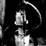 “A DREDGER IN THE WELL”
From month to month postponed the cleaning of the well from the accumulated in the bottom of a layer of silt. To do this work alone, and even two traditional methods (bucket and spade)...
