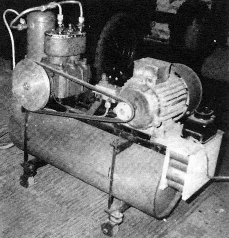
The compressor unit may not be as essential in a home workshop or a car enthusiast’s garage as an electric drill or a vise. However, when such a unit is available, it greatly simplifies some labor‑intensive operations (such as inflating tires) and can significantly improve the quality of work (for example, when spray‑painting parts). Wherever work is carried out with pneumatic tools, and electric mechanisms (even low‑voltage ones) are strictly prohibited for safety reasons (in fire‑hazardous or explosive areas), a compressor is simply indispensable.
This compressor unit was built almost “by itself” — there was no urgent need for it at that moment, but several components and mechanisms suitable for such an aggregate had accumulated in my home workshop “arsenal”.
Later the unit served me very well, especially when applying multiple paint layers to my country house. Without it I would have spent incomparably more effort and time on this job, not to mention increased paint consumption and poorer finish quality. Before and after this “major” project, I have regularly used the unit to inflate tires of various vehicles (a passenger car, a small truck), to paint large‑sized items, and for pneumatic riveting when joining parts of homemade structures, etc.
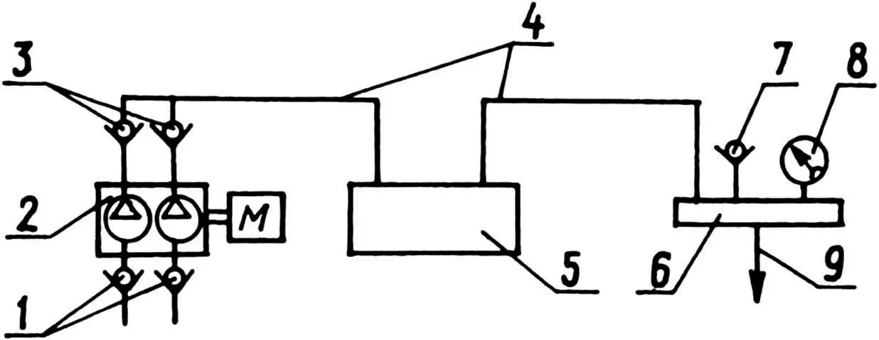
1 — intake valves; 2 — two‑cylinder compressor driven by an electric motor; 3 — discharge valves; 4 — tubes; 5 — receiver; 6 — distribution box; 7 — safety valve; 8 — pressure gauge; 9 — compressed‑air outlet pipe
The main mechanism is a two‑cylinder compressor from a ZIL‑130 truck, which became the “heart” of the unit. The main structural and load‑bearing element of the assembly is a muffler from a KrAZ truck. In the unit it serves as a receiver; a simple frame made of 35×35 angle steel is mounted on it, and all components and mechanisms are fixed on this frame. Two cross‑members made of the same angle (each connected to the frame by a pair of studs) are placed under the receiver, and four self‑aligning wheels are attached to their ends.
To convert the KrAZ muffler into a receiver for the compressor unit, the inlet and outlet pipes were welded shut with end caps. Then two threaded M14x1 holes were drilled in the outlet‑pipe cap, and two fittings were screwed into them using sealant.
Initially, an intermediate receiver was also installed, made from a small oxygen cylinder, intended to “trap” moisture and oil present in the compressed air. However, its efficiency turned out to be rather low, so later I made a drain threaded hole in the bottom of the muffler‑receiver, closed it with a tight plug, and removed the small cylinder from the design.
As the compressor drive I used a three‑phase AC electric motor rated at 1 kW with a shaft speed of 1380 rpm. Its windings are connected in a “delta” configuration and adapted to run from a 220 V household power supply. Of course, it would have been better to install a smaller, single‑phase motor, but, as often happens with home‑builders, I used and adapted what I already had.
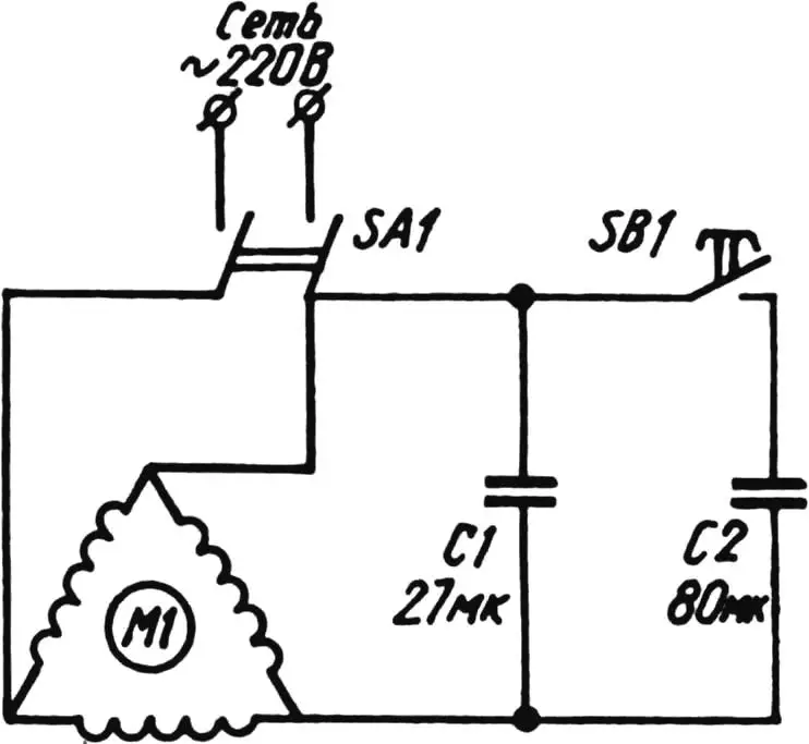
To ensure that the motor starts easily and does not overheat during operation, I had to select both a starting and a running capacitor bank and connect them according to the given diagram. The starting box was taken from a “Kama” type washing machine. The motor is started as follows: first the button for connecting the starting capacitor bank is pressed, then the main start button on the switch is pressed. After the motor reaches its rated speed, the starting‑bank button is released. The motor is stopped by pressing the “Stop” button.
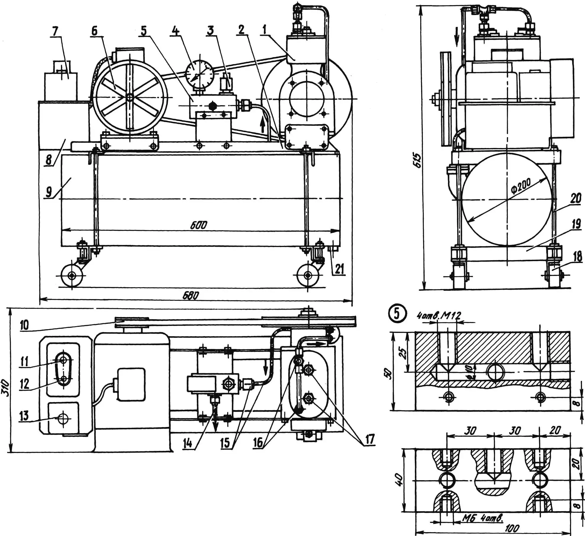
1 — compressor (from a ZIL‑130 truck); 2 — frame (35×35 angle steel); 3 — safety valve; 4 — pressure gauge; 5 — distribution box; 6 — electric motor (three‑phase, N = 1 kW); 7 — starting box (from a “Kama” washing machine); 8 — capacitor bank; 9 — intermediate receiver (oxygen cylinder); 10 — V‑belt drive; 11 — “Stop” button; 12 — motor start button; 13 — button for short‑term connection of the starting capacitor bank; 14 — fitting of the discharge (outlet) pipe; 15 — 10×2 pipelines with fittings; 16 — discharge valves; 17 — intake valves; 18 — self‑aligning rubber wheel (4 pcs.); 19 — cross‑member (35×35 angle, 2 pcs.); 20 — M10 tie stud (4 pcs.); 21 — drain‑hole plug
The capacitance of the running capacitor bank is chosen so that the motor does not heat up even during prolonged operation. For a 1 kW motor it is 25–30 µF. The starting‑bank capacitance in this case is from 70 to 100 µF. The main selection criterion is fast motor acceleration to operating speed. All capacitors must have a breakdown voltage of at least 300 V.
For better cooling of the electric motor, a homemade six‑blade fan enclosed in a protective cylindrical shroud is mounted on the motor shaft.
Power is transmitted from the electric motor to the compressor eccentric by a V‑belt drive that reduces the rotational speed by roughly a factor of three.
To reduce the power consumption of the drive (that is, to ease its operation), the compressor had to be slightly modified. Instead of the stock head with only two discharge valves (air intake was performed through ports in the lower part of the cylinders, which had to be sealed), a duralumin plate with four valves was installed: intake and discharge pairs.
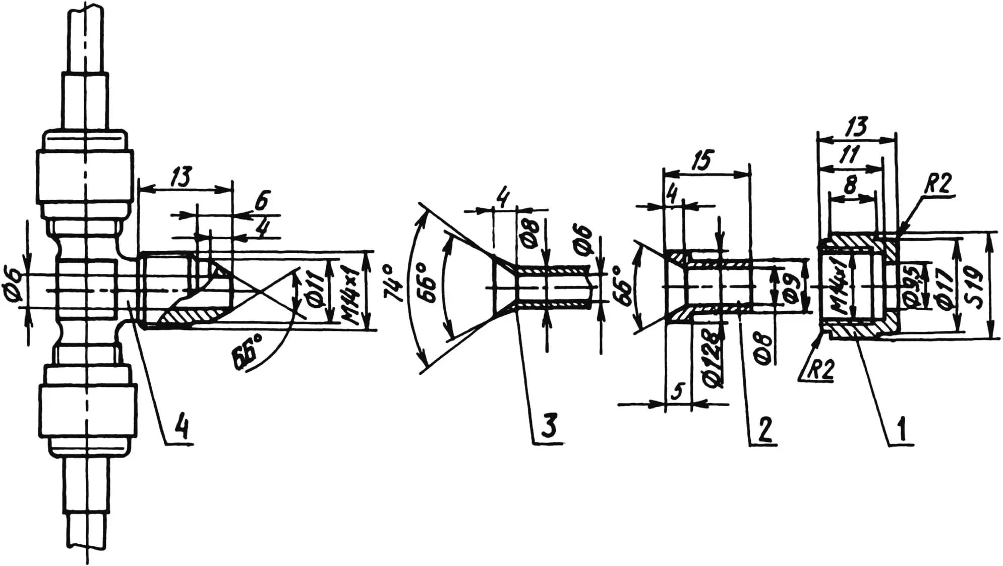
1 — M14x1 union nut; 2 — sleeve; 3 — pipeline (aluminum tube 8×1); 4 — M14x1 fitting (tee)
The pipelines connecting the compressor to the receiver and to the distribution box are aluminum, with a through diameter of 6 mm. Their connections to the mechanisms are made using standard aviation fittings, elbows, tees, and union nuts with sleeves.
The distribution box is homemade: it is an aluminum block with a blind longitudinal hole, 10 mm in diameter, drilled from one end in the middle; a tube from the receiver is connected to this hole via a fitting. Three more holes of the same diameter lead into this cavity: two from above and one from the side. One top hole houses a pressure gauge, and the other contains a safety valve set to a maximum pressure of 4 kg/cm2 (4 atm). A compressed‑air outlet pipe is installed in the side hole.
“Modelist‑Konstruktor” No. 8’2003, E. EVSIKOV
Recommend to read
 HANDLE WITH KNOB
no matter How Limeray the length of the wire cord, all the same thread sizes is not exactly the same. To the neutral position of the Elevator corresponds to the vertical position of the...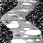 CONCRETE PATTERNS ON THE TRACKS
Beautiful and elegant look of Park paths, lined with small plates. Why not adopt a similar method of covering tracks in the garden area? Because concrete is more durable and clearly...
