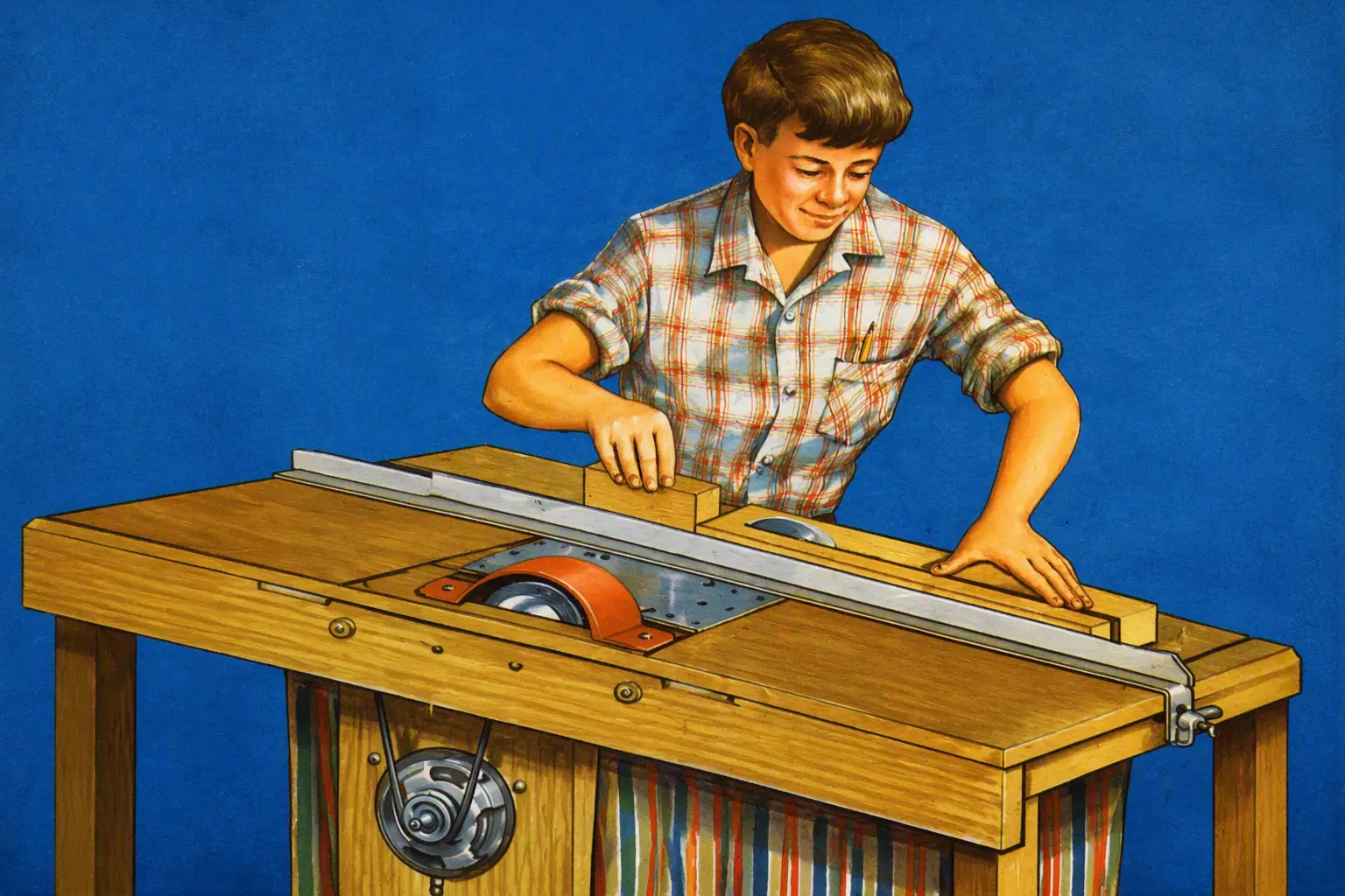
This machine can indeed be made from an old table, and it really is a whole workshop: our reader, engineer B. Popov, who built it, provided for interchangeable working tools — here you will find a circular saw (1), a grinding stone (4), a planer rotor (3), and even a lathe setup (2).
Replacing hand tools with mechanical ones is of great importance not only in industry, but also in the home work of an amateur designer who turns ideas into wood and metal. Sometimes even the simplest fixtures and primitive small machines can greatly speed up the work, make it easier, and sharply improve the quality of the product. That is why, recently, more and more miniature machines for working wood and metal, designed for home craftspeople, have been appearing.
Many original designs have been created by enthusiasts of technical creativity. One of them — a universal machine designed by engineer V. N. Popov — we offer today to our readers’ attention.
The machine is very simple, and its main components are sold in stores as spare parts for household appliances. After building such a machine, you will be able to perform longitudinal and cross cutting of wood, plastics, and sheet metal; planing and turning of wood; milling, grinding, and polishing of various materials; and sharpening of cutting tools.
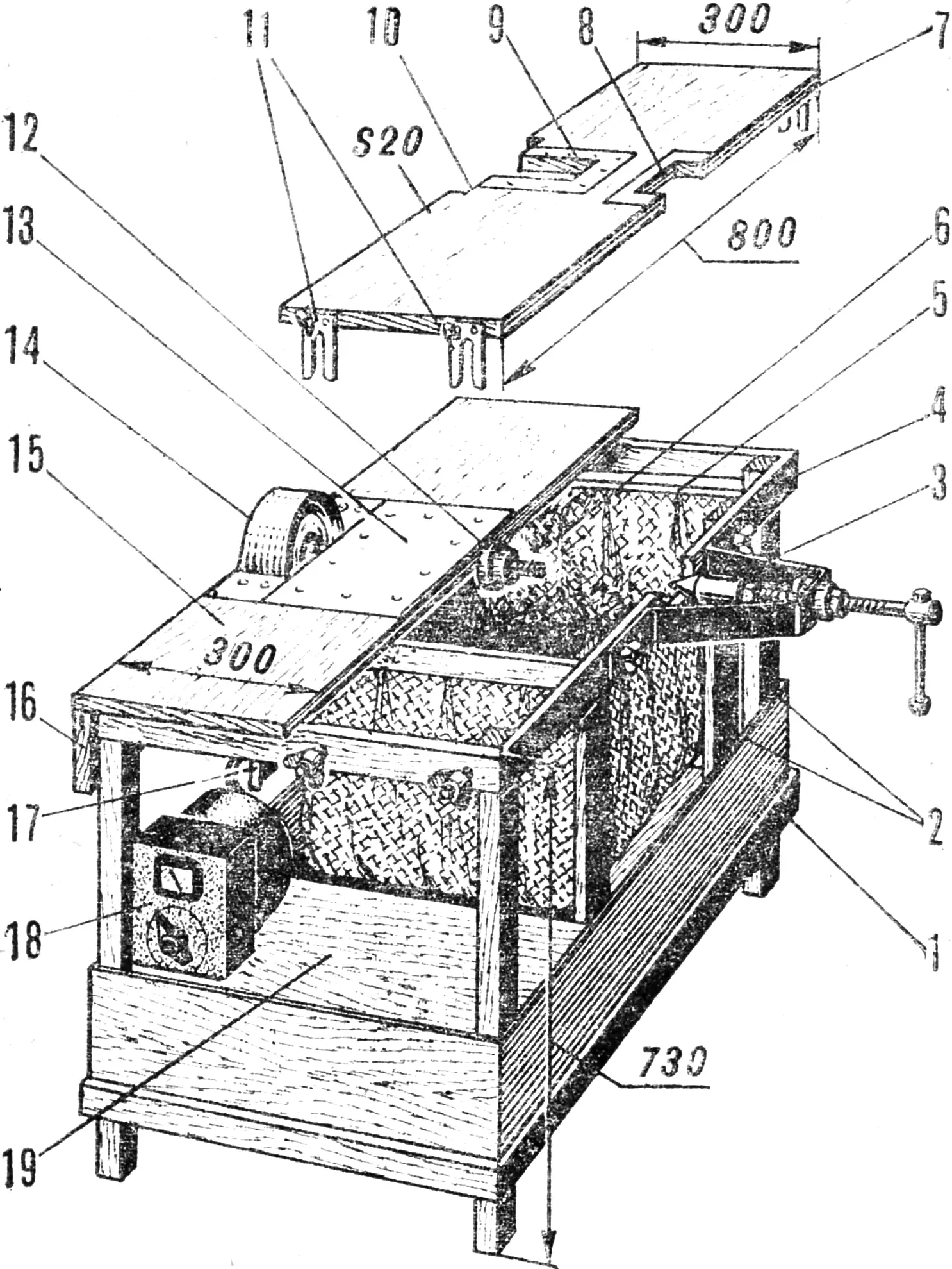
1,4 — lower and upper frames, 2 — uprights, 3 — tailstock, 5 — cross member, 6 — bag, 7 — reversible table panel, 8 — small panel cutout, 9 — metal plate (with a slot for the planer head), 10 — large panel cutout, 11 — panel lift brackets, 12 — spindle, 13 — metal plate, 14 — pulley guard, 15 — hinged panel, 16 — drive guard board, 17 — motor suspension panel, 18 — autotransformer, 19 — box.
To build the machine you need to obtain: an AC electric motor (similar to those installed on domestic vacuum cleaners) rated at 500 W, 12—1400 rpm, for 220 V; two angular-contact bearings No. 36203 and 36204, or correspondingly 46203 and 46200; two pulleys Ø 135 and 60 mm for a V-belt of profile 0. (They are sold as spare parts for washing machines.)
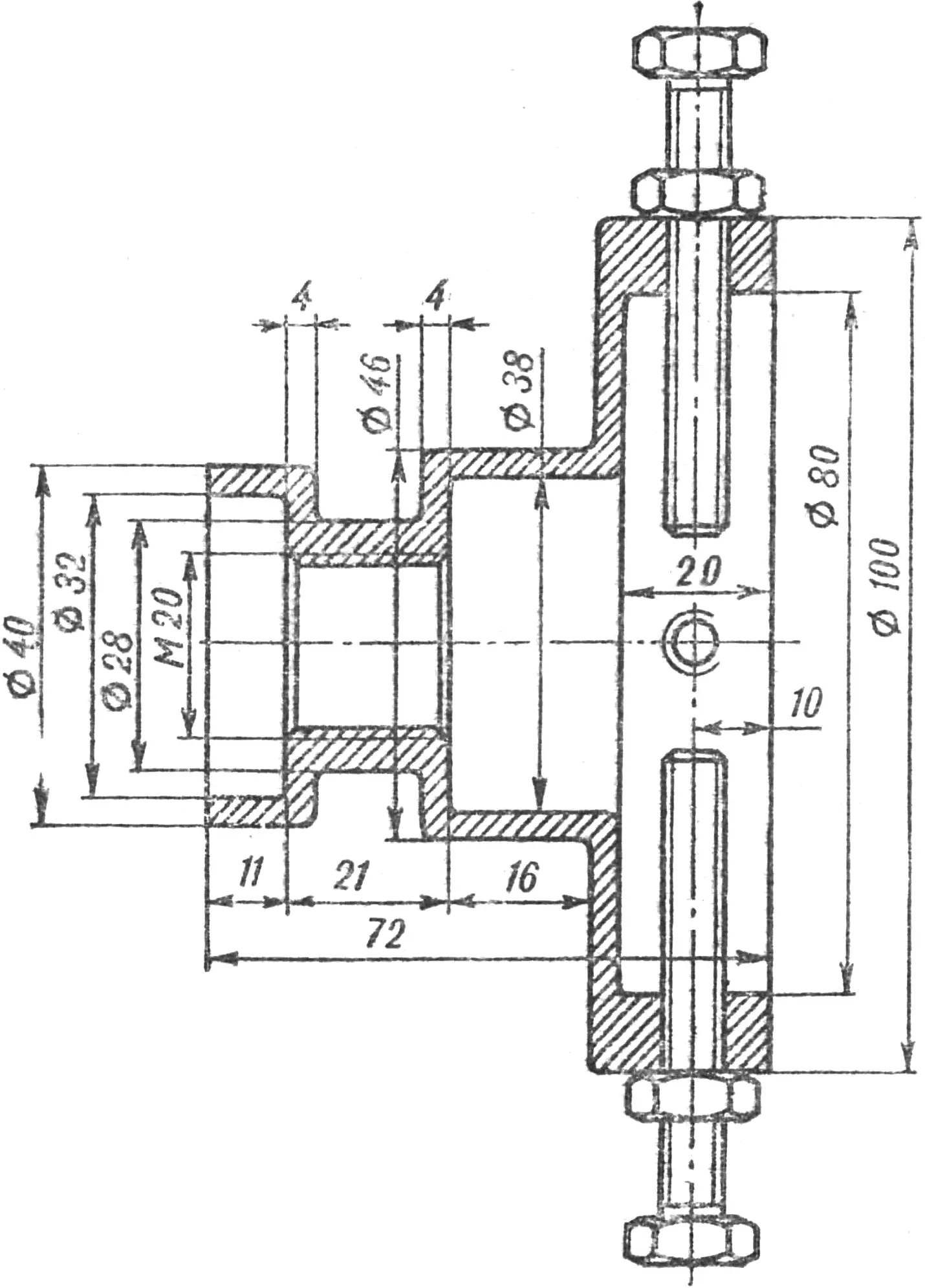
The general view of the machine is shown in Figure 1. Its main part is the spindle. The mounting surface for installing the required tool on it is a journal Ø 32 mm. The tool is secured on the spindle with a shaped clamp and two nuts.
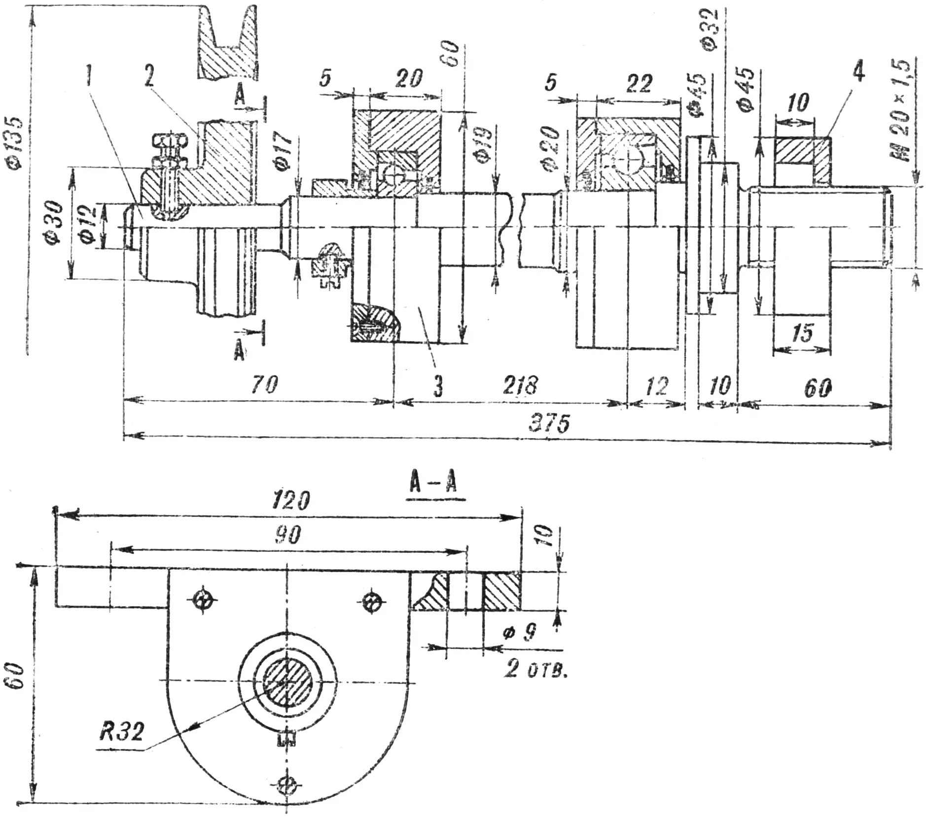
1 — spindle shaft, 2 — pulley, 3 — bearing housing, 4 — clamping washer.
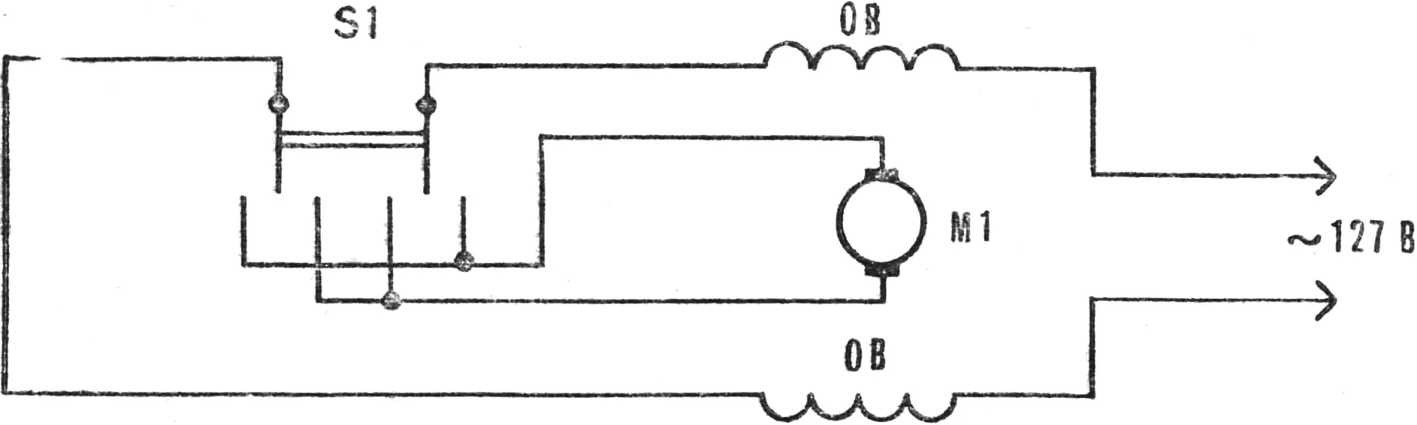
If the machine drive is to be installed to the right of the operator, a left-hand thread must be cut on the spindle; with a left-hand layout, a right-hand thread is cut on the spindle. In that case you will also have to reverse the rotation of the electric motor rotor by reconnecting the windings and brushes. Such switching may be made permanent, or a P2T-1T type switch may be introduced into the circuit to obtain reverse.
The machine table is made of thick plywood or furniture board. It consists of left and right halves, each 300×800 mm. In the middle of the left half of the table, the spindle is mounted on M8 countersunk-head bolts, and the panel itself is fastened to the upper longitudinal beam of the frame on door hinges. The other side of this panel is held by hooks installed on the front and rear cross members of the frame. This provides easy access to the machine mechanisms for inspection and repair.
Depending on what is available, the frame is made of wood or steel angle (welded, or bolted). For this purpose you can use the frame of an unusable table or workbench, etc. The height of the frame with the table is 750 mm from the floor. In its lower part it is desirable to provide a box for storing tools and workpieces.
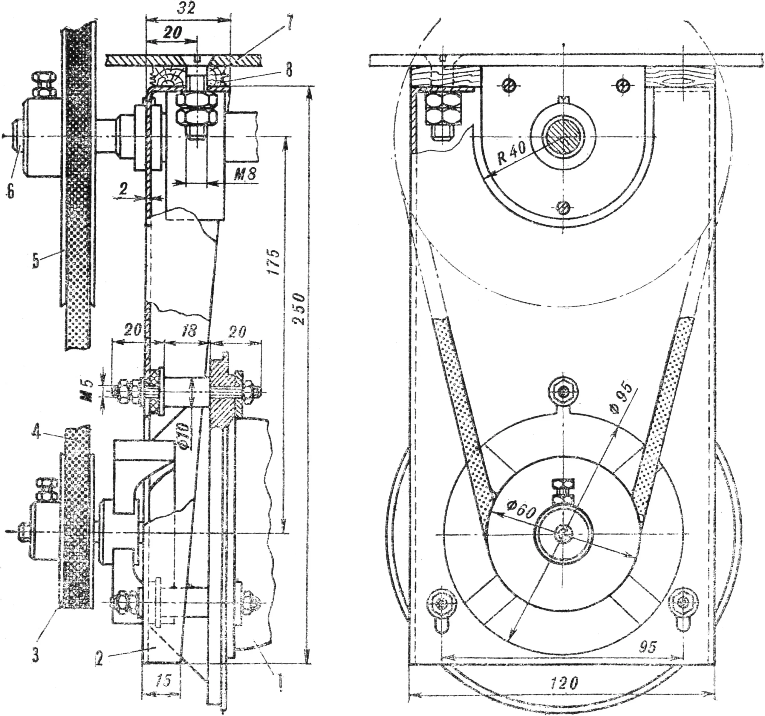
1 — motor, 2 — motor suspension panel, 3 — motor shaft pulley, 4 — drive belt, 5 — spindle pulley, 6 — spindle, 7 — metal plate, 8 — table panel.
The electric motor is mounted on a plate of 2 mm sheet steel. It has a scoop-like shape and is provided with a slot for the passage of the spindle’s rear bearing housing, an opening for the front part of the electric motor with the pulley, and three slots for fastening the motor stator and tensioning the belt. Instead of the factory bolts that fasten the motor cover to the stator, three studs must be made. With their right-hand side the studs secure the cover to the stator; with the left-hand side they secure the motor to the plate. For cushioning, a rubber gasket is placed between the plate and the washer. All part dimensions on the drawing are given for the electric motor from a “Buran” vacuum cleaner. When installing others, they will naturally have to be changed. The plate with the motor itself is mounted under the same bolts that fasten the bearing housing to the cover.
Installing the right half of the table top on the frame presents no particular difficulty. It is only important that it can be turned over, because on one side it must have a slot for a narrow cutting tool (a circular saw, a grinding wheel with glued-on sandpaper, etc.), and on the other side — for a wide tool (for example, a grinding stone or a polishing head).
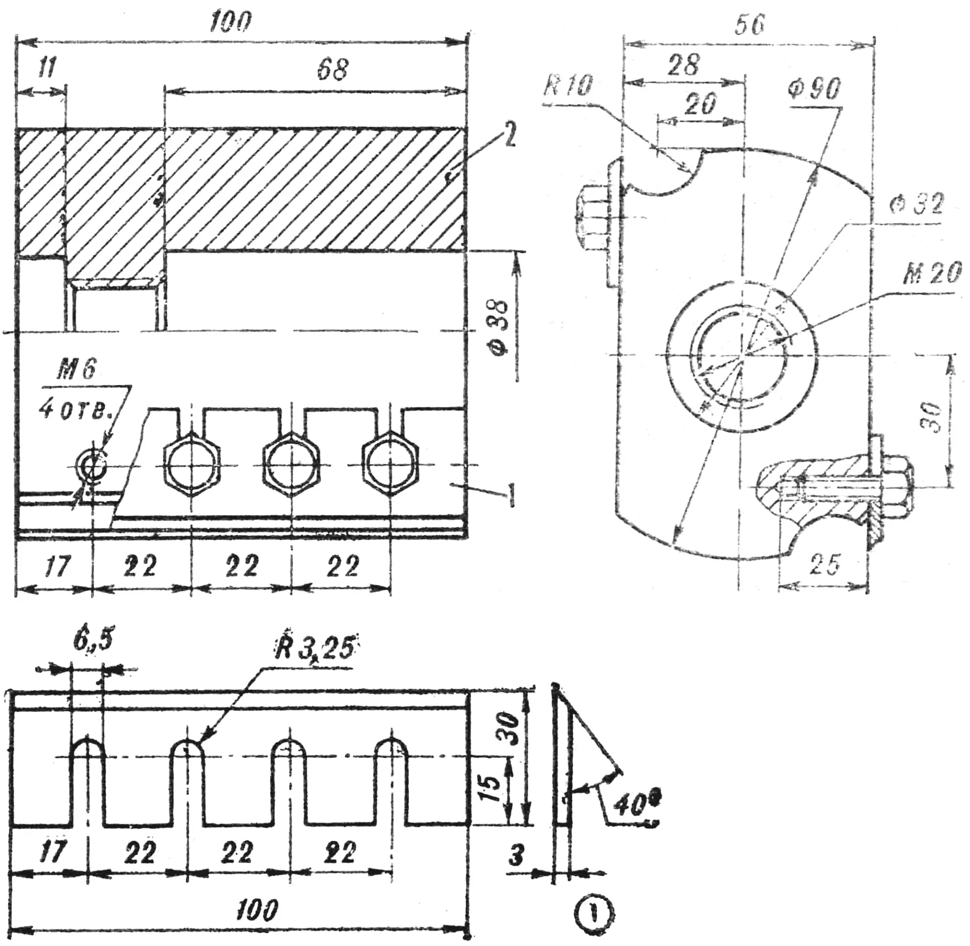
1 — knife, 2 — drum body.
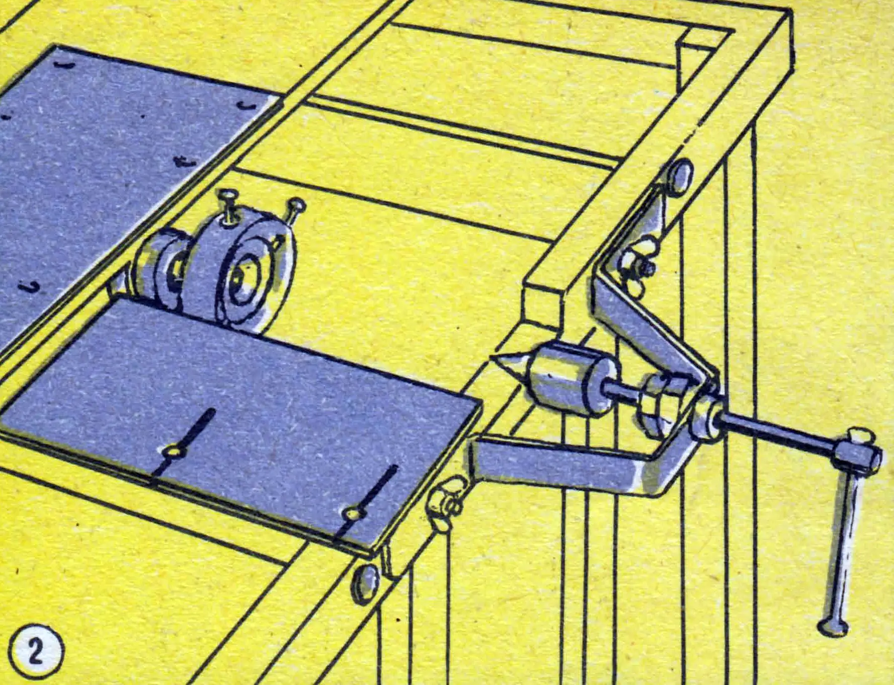
For woodturning, a four-jaw chuck is mounted on the spindle, and a removable tailstock is mounted on the frame. The chuck is screwed onto the spindle and locked with a nut. M8 bolts serve as the jaws. The tailstock consists of a bracket in whose center (in a welded-on nut) a screw with a handle travels. A live center or a drill chuck is fitted on its free end. The dimensions of the spindle chuck and the tailstock must match the size of the workpieces intended to be machined on the lathe, as well as the sizes and mounting seats of available or purchased parts — the live center and the drill chuck. It should be borne in mind that for some woodturning jobs a chuck on the spindle is not needed; a simple “fork” may suffice.
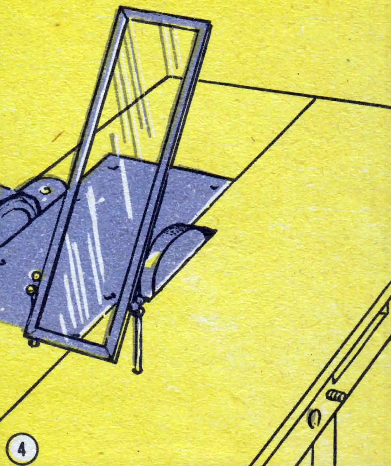
Almost all the cutting and grinding tools an amateur needs are now available commercially, including circular saws from 200 mm in diameter and abrasive wheels of various grit sizes. But when making the frame, provision should be made for mounting Ø 300 mm wheels with sandpaper glued onto them on the spindle — for grinding work.
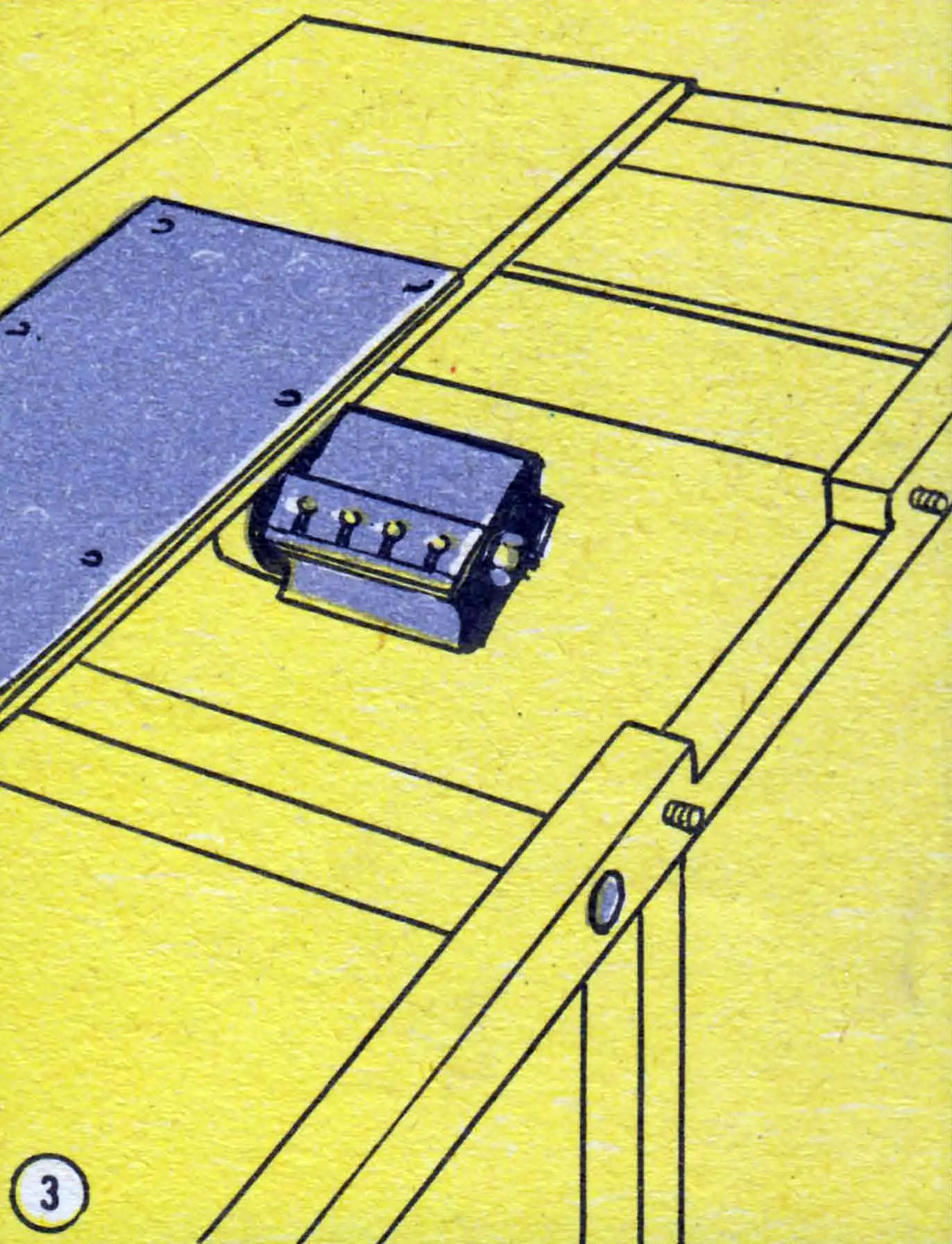
The design of the proposed machine makes it easy to turn it into an electric planer. To do this, make a cutter drum and knives from steel. Steel 20 is suitable for the drum; the knives should be made from steels of grades KhVG, R-9, 9Kh5VF, or R-5 (85Kh4V4F) with heat treatment to HRC 55—59. To simplify knife manufacture, they can be cut from the blade of a wide chisel using cutoff wheels on this same machine.
Cutter drums are usually mounted on two supports, and it may seem that the reliability of the proposed cantilevered drum design is reduced. However, if one compares the peripheral force of the electric motor, equal to 2.4 kg, with the force of the operator’s hand, taken as 15—16 kg, then at the slightest increase in feed the motor will stall. The motor’s small torque reliably protects the machine from any overload capable of causing damage.
For high-quality wood planing, correct knife sharpening is of great importance. With a large sharpening angle, resistance increases, leading to overload and overheating of the electric motor, while with small angles knife life drops sharply and they dull quickly. It is very important that the tool be sharpened uniformly along its entire length. Holding the knife in one’s hands, it is practically impossible to sharpen it correctly. Therefore a simple fixture must be made. It is mounted on two wooden panels, and its design needs no explanation. For setting the sharpening angle correctly, a protractor is fastened to the lower panel. Such a fixture can also be used for sharpening other tools.
For operations such as cutting a groove, a rabbet, and various slots, a rising table is installed; its design may vary depending on the materials available. It should be noted that the slots in the table-lift brackets were made on the same machine using abrasive cutoff wheels. For planing work it is advisable to have a separate table with a more solid fastening to the frame, because vibration may occur during operation and produce ripple on the planed surface.
Chip and sawdust collection during machine operation is provided by a waste collector suspended under the table top. It is made of dense fabric or leatherette. The noise level during operation can be greatly reduced by including an autotransformer voltage regulator rated at no less than 250 W in the electrical circuit. Operations such as tool sharpening, grinding, polishing, and cutting rabbets and grooves can be performed with the motor supplied at 70—90 V; the spindle then runs at 1300—1800 rpm. For longitudinal and cross cutting, metal cutting, and lathe work, 100—120 V is sufficient (correspondingly 1700—2000 rpm). For planing work — 115—127 V (2500—3000 rpm). Naturally, the feed rate is also selected according to the motor operating mode.
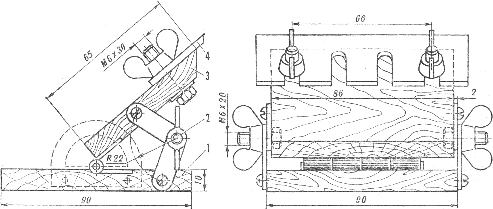
1 — base, 2 — hinged bracket, 3 — knife mounting bar, 4 — knife.
If, under the working conditions, machine noise is of no great importance, 127 V is supplied to the electric motor. It must not be connected to a 220 V mains, because it overheats quickly and begins to run away.
It goes without saying that working on the proposed machine requires the strictest observance of safety rules. Thus, the circular saw and the planer head must be fitted with guards of the usual type; grinding, abrasive, and cutoff wheels are enclosed by a frame with organic glass. The planer head requires special attention. Before starting work it is necessary to check the fastening of individual parts, the tightness of threaded connections, and the sharpening of the knives. Sharpening — if required — must be done only on the back face of the knife, on a special fixture, and overheating must never be allowed. To avoid unbalance and vibration of the drum, the knives with their fastening parts are selected so that the weight of one set does not differ from that of the other by more than 5%. Correct installation is checked with a straightedge pressed by its working edge against the table. The cutting edges must then be set for a planing depth of no more than 2 mm. After aligning the knives, which have first been lightly drawn up by screws to their seats, the fastening screws are tightened firmly, starting with the middle ones.
In all other respects, the general rules for operating machine tools should be followed.
“M-K” 6’83, B. POPOV, engineer
Recommend to read
 “DONKEY” ASKS THE CAMPAIGN
UNIVERSAL TROLLEY FOR TOURISTS-WATER-TRANSPORT WORKERS. Over the years Hobbies boating, we tested several variants of trucks for transportation of kayak and equipment. And the hikes have... DIVIDE INTO THREE PARTS
It is known that most of the screws ships — lobed, And consequently, when playing them on-models necessary to accurately mark the three holes on the propeller hub, placing their centers...
