To purchase for these purposes the factory circular saw in connection with the frequency of work is not only expensive, but also problematic for its storage requires space, and unnecessary in a city apartment.
Being in such a situation, I made simple, small, and even portable “circular saw” driven by a drill motor. After the next use of the unit quickly and easily dismantled into separate elements, which are stored in the tool locker, and the drill is still used for its intended purpose.
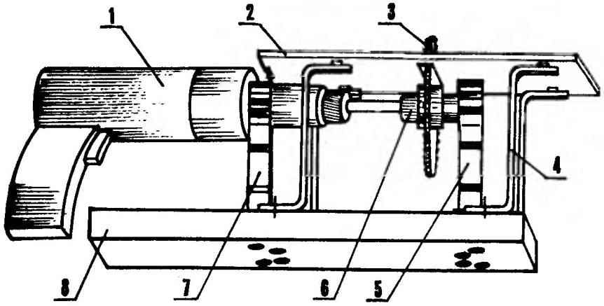
The whole structure (without drill) consists of a base, a work table, four pillars between two holders: an actuator (electric drill) and the free end of the shaft of the saw blade.
For base used furniture (lined) chipboard size 300×250 mm and thickness 30 mm.
Table (working plates) are made of hard duralumin plate of thickness 4 mm and approximately in the middle transverse cut groove dimensions 160×10 mm (for the maximum prospective for the use of the saw blade diameter, I — 160 mm). The table can be made of sheet steel roughly the same thickness, but then the whole construction heavier. But chipboard to use for this purpose is not desirable for providing the stiffness, its thickness must be considerable, and it is, consequently, reduce the maximum thickness of the sawn workpieces.
Layout drills”saws”:
1 — drive (electric); 2 — Desk (duralumin, sheet s5); 3 — saw; 4 — (St3, strip 20×5, 4x); 5 — bearing shaft mount mandrel; 6 — frame; 7—the holder of the drill; 8 — support plate (furniture chipboard, s30)
Holder drills — improvised. It is made of steel plates section 20×5 mm Holder comprises two legs and a terminal clamp formed by a pair of brackets with ears. The radii of the brackets on the cylindrical part of the housing of the drill. The bottom bracket is riveted to the upper ends of the legs by steel rivets with diameter 4 mm. Holes in the bracket and countersink the rivet heads it made wpoty. In the ears on both brackets, drilled the appropriate holes for M8 bolts, which are tightened, clamping and locking drill. In the upper bracket holes were made in advance, and at the bottom — the place (as in the conductor— for the top bracket). The same holes drilled in the legs of the uprights. The shaft mount is picked up ready, although it can be done exactly the same as the holder of the drill.
Four pillar “buzz-saws” made from the same material as the holder,— steel strip section 20×5 mm. Their horizontal legs at the ends, as the letter Z, bent in different directions. The legs are drilled the holes for the M8 bolts. In the manufacture of racks there is one complicating factor — the determination of their height. It must be such that the edges of the cheeks, pinching the saw blade and an electric drill Chuck, did not touch the bottom plane of the working plate, but the plate should not above them to rise much, again reducing the maximum thickness of the sawn workpieces.
Relatively complex site, “the saws” — mandrel, consisting of a drive shaft of the saw blade with the locking parts of the latter. The shaft is stepped. The diameter of its left side, however, as its length, defines the maximum possible size, clamping electric drill Chuck. The diameter of the next stage slightly increased, and in the third stage with a diameter of 25 mm made of flats under the open-end wrench.
Holder (drill shaft):
1 — leg (St3, strip 20×5,2); 2 — rivet (steel, d4); 3 — bolt M8 with nut (2 PCs); 4 — lower bracket (STZ, strip 20×5); 5 — upper bracket (St3, strip 20×5)
The next step is a flange. Its diameter (in my design — 42 mm) is selected so that the flange, together with a special clamping nut M10 provided reliable clamp (hold the friction) of the disk saws.
Next is the part on which is mounted a circular saw blade with a minimum bore 12,6 mm Disks with large bore holes are installed on this part using adapter rings.
This is followed by the step cut on it with an M10 threaded hole. Her’re in for a special clamping nut, the diameter of larger stage which is the same as that of the flange. On a smaller level of nuts (with outer diameter 25 mm) and the nut is filed off the flats under the key “on 22”, and the third stage of the shaft. Pressure nut is insured against the loosening of the special nut, although actually it is possible only after turning off “buzz-saws” with the free rotation of the mandrel due to the inertia of rotation of the saw blade of large diameter.
At the end of the shaft axle is made with a diameter of 7 mm bearing 80027 sizes 7x22x7 mm (dхDхВ, where d— internal diameter D — external diameter, B — width). Bearings 80 series two shields, because the wood dust if you work here very much. The bearing is placed in the body which, in turn, is connected between terminal clamps of the holder. In the body, except the landing bearing housings, drilled a through hole through which the shaft stands out when disassembling the node. In the node can be used and suitable bearings with double seals series 180. Bearings if either of the other series are not available, the unit should provide the protection of conventional bearings with seals or cuffs.
All parts and components of the “circular saw” fastened together with M8 bolts with countersunk heads (except for terminal clamps — they are bonded to conventional bolts). Heads recessed into the body parts flush (from the bottom of the base plate and the top of the desktop) and do not represent interference with the installation of “circular saw” on any suitable table and work on it.
Assembly “buzz-saws” was performed in the following order. First, the housing with the inserted bearing clamped in the holder terminal. Next on the shaft is secured a circular saw blade. For this purpose, the shaft is clamped in a vise for a key to the flats and put on the seat ring (or rings) and the disk (teeth in the direction of rotation of the shaft). The threads screw the clamping nut and the locknut. Then the holder is secured the drill and its patron — the corresponding end of the shaft of the mandrel. The other end of the shaft inserted in the inner hole of the bearing.
Then on the basis of drew the axis of symmetry and along it placed together drill, mandrel holders. Here, at the base, marked the holes for the mounting legs of the holders and drain. Drilled holes, razinkovas them from the bottom, insert the M8 bolts with countersunk heads and fastened on top of the leg holders and rack nuts. The upper location of the screws ensures easy Assembly, adjustment and disassembly of stanochek.
Then put the rack on the Desk so that the saw blade included in it a slit-groove have the same clearances from the edges. The holes in the upper legs stands at the bottom of the table spaced response centers of the holes, drilled them and razenkova from the top side under the flat head bolts M8. In the process of fixing the table stands on its position relative to the disc exposed even with the washers, placing them between the foot stands and a working stove and putting on the rod bolts.
To operate the circular saw on its base fixed to the workbench with clamps to the drill was on the left side, and the end of the handle in an inclined position relied on the table of workbench.
The bearing housing (St3, rod d44)
Mandrel:
1 — shaft (steel 45, rod d44); 2,3,4 — adapter rings (St3); 5 — circular saw blade; 6 — clamping nut M10 (St3, rod d44); 7 — special nut M10 (St3, rod d25)
Short inclusions of drill, check runout of the saw blade and eliminates them restoring the alignment of the drive units by lining cups from sheet metal in the terminals and washers under the foot holders.
The design of the “circular saw” allows you to set on its arbor circular saw blade maximum diameter of 160 mm and to cut the workpiece thickness up to 50 mm.
If necessary, for maintaining the accurate and constant width of the cut portion of the workpiece on the work plate can be set from the guide cut a metal bracket securing bolts through the appropriate slots in it.
When working on drills-“circular saw” it is necessary to observe some simple safety rules. Feeding of the workpiece it is necessary smoothly, without distortions, avoiding stopping and jamming of the saw blade. Before stopping the mechanism it is necessary first to contact the workpiece and the drive and then turn off the drill.
D. DVOENOSOVA
Recommend to read OUTDOOR — TABLE The use of floor brush in certain cases uncomfortable. I propose to make a one-handed floor brush from a table, the so-called intelligence — it is used to smetana shavings from the... COTTAGE ON WHEELS Offer readers a description of the design built my trailer. The creation of this garden on wheels gave me the tools and guidance previously published in the journal (for example, No. 8...
Scroll back to top
 In the household from time to time there is a need for longitudinal sawing long boards on the bars or slats, trim, particle Board (chipboard) size or production of similar transactions with other similar building or furniture materials. Who performed such work with a hand saw, he knows how it is tedious, and difficult job, especially when such cuts necessary to make a few or have to work with wood, or cut the old particle Board with a lacquer finish, which stiffened the binder, and the coating is vitrified.