Sometimes even a reliable electric drill fails. As statistics show, failures occur not so much in its mechanical part as in the electrical part. But while there are many published tips on restoring the power cord, replacing worn brushes, a faulty switch, or fixing other simple malfunctions of household appliances, including on the pages of “Modelist-Konstruktor” (see, for example, No. 9’95, 6’96, 2’97), the same cannot be said about more complex types of repairs. In particular, there is a clear lack of materials on the features of maintenance and feasible (in a home workshop) repair of the rotor of collector motors, usually installed in drills, impact wrenches, and other hand-held power tools.
Unfortunately, there are quite a few peculiarities. It is hardly possible to understand them without grasping the design and operating principle of collector motors (Fig. 1). It is also useful to recall that, according to the laws of physics, a force F acts on a conductor with current I in a magnetic field of intensity H, the direction of which is determined by the so-called left-hand rule. Moreover, judging by the simplified diagram, the maximum torque is created when the current-carrying turn is exactly between the poles of the electromagnet.
However, a real motor develops maximum power when the working turn (lap winding) is positioned at an advance angle (commutation angle), which for a drill is approximately 45°. In this case, the alternating current after the electromagnet flows to brush A, passes to commutator segment A, and then, through the turns of the lap section, to segment B. But the latter is electrically connected to its antipode—segment B’—from which the current flows through brush B into the power supply network.
Single-phase collector motors of most hand-held machines are non-reversible, meaning they rotate only in one direction, determined by the specific connection scheme. The brushes are positioned with a shift from the geometric neutral by one to two commutator divisions. The shift angle is determined experimentally by minimizing sparking at the working surface of the commutator under rated load for the required direction of rotation. In reversible motors, usually used to drive thread-tightening machines, the brushes are set at the geometric neutral.
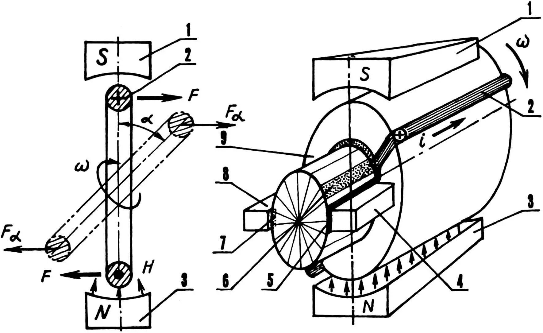
1 — south pole of stator electromagnet; 2 — rotor lap winding («+» — conventional representation of current directed toward the drawing plane, and «·» — away from it); 3 — north pole of stator electromagnet; 4 — copper-graphite brush A; 5 — segment A; 6 — segment B; 7 — segment B’; 8 — copper-graphite brush B; 9 — rotor; а — advance angle (commutation); Н — magnetic flux; F — force acting on a current-carrying conductor in a magnetic field (determined by the left-hand rule); Fα — force acting on the lap winding taking into account the commutation angle; і — electric current; ω — angular velocity of rotor rotation
Runout of the commutator surface is checked during motor maintenance with a dial indicator while slowly rotating (manually!) the armature or rotor of electric machines. If the motor is disassembled, the armature or rotor is mounted in centers and also rotated. During measurements, the indicator tip is set perpendicular to the commutator surface. The runout value (which, as a rule, should not exceed 0.05—0.06 mm) is determined by the difference between the maximum and minimum readings of the instrument.
Profile control is also a very important element in determining the technical condition of the commutator. This operation is performed visually, paying attention to the depth of the micanite spacers between segments, which should be within 0.3—0.5 mm.
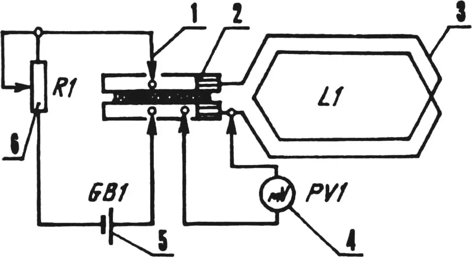
1 — electrical probe (4 pcs.); 2 — commutator with segments; 3 — lap winding under test; 4 — pointer millivoltmeter; 5 — galvanic battery; 6 — variable resistor; ratings of elements 4—6 are determined during preliminary circuit setup
Solder defects or breaks are usually determined by measuring voltage drops at the connection points of commutator plates with the armature winding (Fig. 2). The connection of lap winding leads with the corresponding commutator plates is considered satisfactory if the voltage drops at the soldering points do not differ by more than ±10 percent of the average value.
Sometimes the windings themselves are so bad that it is advisable to replace the entire rotor (armature) with a new one. Well, if such a possibility does not exist, one has to resort to rewinding even in a home workshop. This is a very laborious task; to perform it, one must have appropriate tools, fixtures, consumables, and, of course, a winding layout diagram (preferably with a circular diagram).
For example, the rotor of electric drill IE1035E1U2 is subject to rewinding. It has XII slots (hereinafter abbreviated as п) and 24 segments (л).
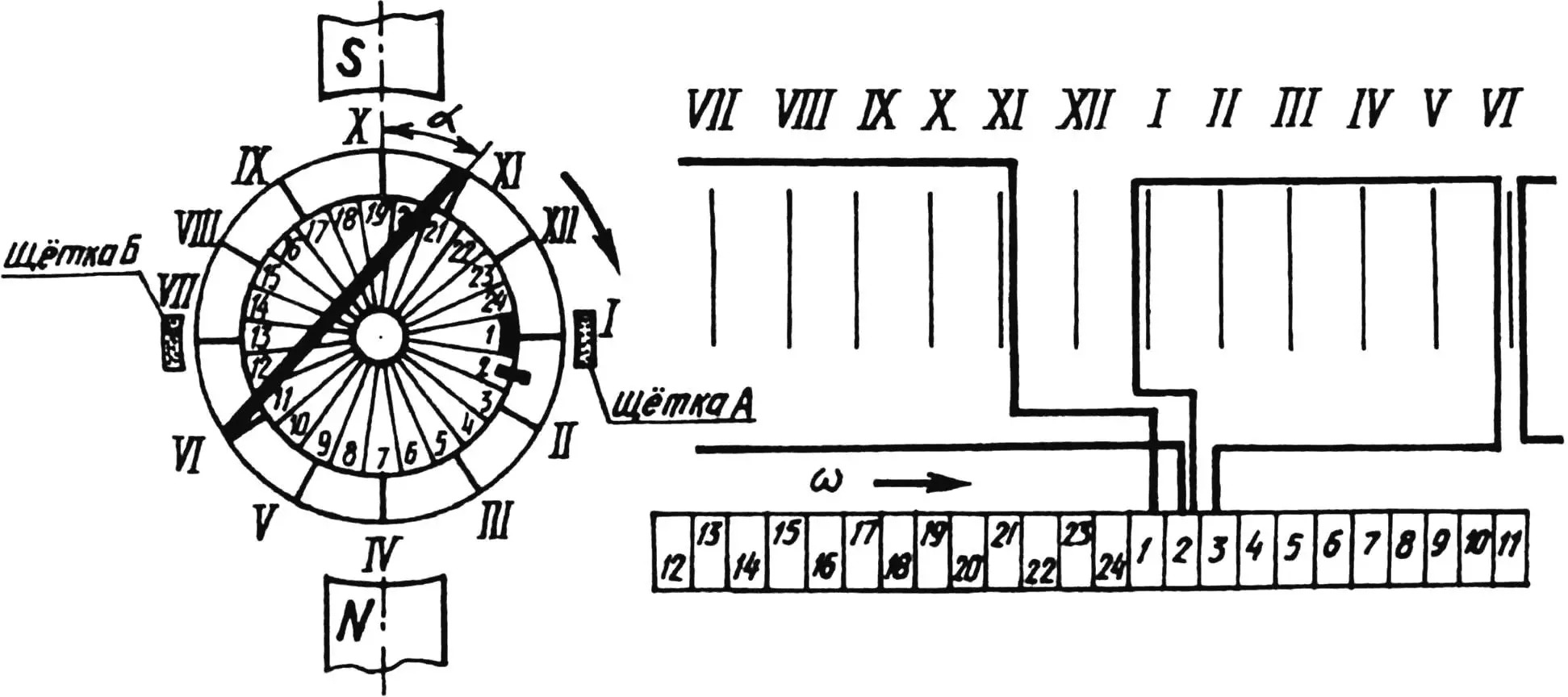
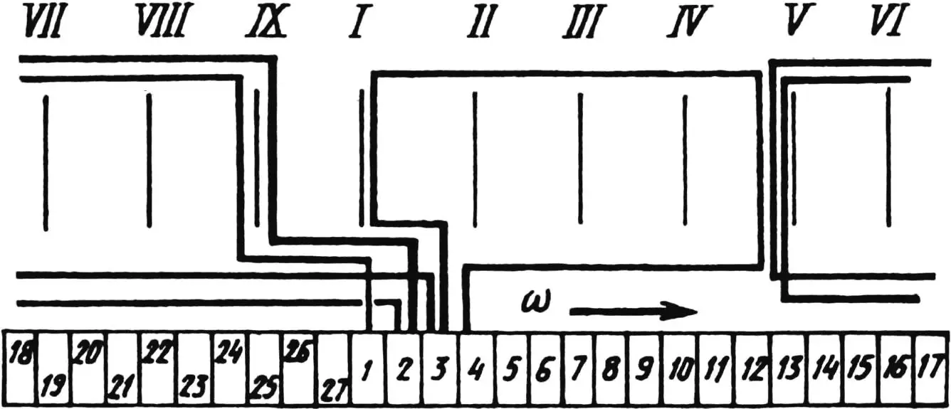
For accuracy, let us use the circular diagram (Fig. 3). Let brush contact segment 1. This means that the section turns must be laid so that they form angle а with the magnetic flux. Whether we use пVI and пХІ or пV and пХII—the commutation angle will be approximately 45°.
Winding must be performed in accordance with the layout diagram (Fig. 3). That is, the turn from л1 should go to пХІ, then to пVI and come to л2. From л2, the winding is directed through slots I and VI to segment 3, and from it (through пХП and nVIl)—to л4, from where (through пll and пVIl)—to segment 5, and so on.
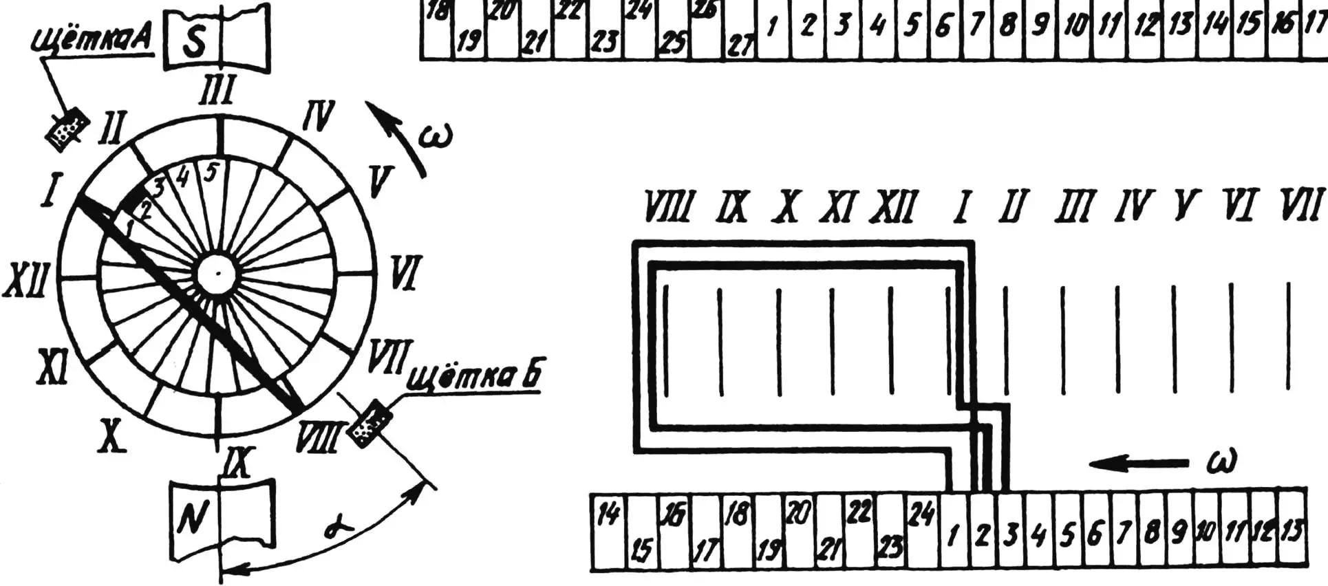
When winding the rotor, some motors may have a situation where not two, but three segments fall on one slot (as in electric drills of type IE1008). There is no need to fear this. One should continue winding, remembering that here sections from three different pairs of segments fall into one slot (Fig. 4).
In conclusion, a few tips. As already noted, refining angle а allows minimizing sparking between the commutator and brushes during operation. Increasing this angle to 75° has almost no effect on motor power.
For insulating lap windings (sections) from the rotor “iron,” it is quite acceptable to use silk (instead of scarce film cardboard). After laying a third of the winding in the slots, it is useful to protect against interphase short circuits. For this, it is sufficient to place another layer of insulation between the turns. For example, from the same silk.
Sometimes the “soldered” hooks on the segments break off. But the profile of each of these parts is such that, by slightly notching the soft base, one can without much difficulty equip them with new mounting elements in the form of catches. And to ensure high quality of subsequent soldering, it is advisable to preliminarily make notches with a chisel at the corresponding places on the segments.
If it is impossible to determine how many turns the failed winding had and what wire was used, for repair and restoration work one can rely on, for example, typical data characteristic of electric drill IE1035. This means that wire PEV2-0.2 will work (though better—with silk insulation, type PELSHO-0.2). Winding—40 turns per section.
When performing winding, it should be taken into account that during operation they will experience quite intense loading. A force of 15 g acts on each gram of wires of the rotating rotor. Hence the requirement: when renewing the winding, it must be impregnated in the slots with epoxy glue.
If after repairing the motor the drill started rotating in the wrong direction, it is necessary to reverse the current direction in the rotor windings. And for this, swap two wires so that the current that went from the stator to brush A (Fig. 1) flows to brush B.
V. ZORIN
Recommend to read
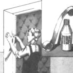 WILL NOT CRACK
Paper tape glued to the joint between the door frame and the wall, protects the knot from cracking and shedding of plaster. Better to glue or PVA Bustilat. D. ZVEGINTSEV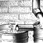 PIGGY RAIN
Most gardeners under the gutters certainly are cumulative barrels to collect rainwater from roofs for irrigation reserve, and in case of fire — water at hand. It's a pity, when the heavy...
