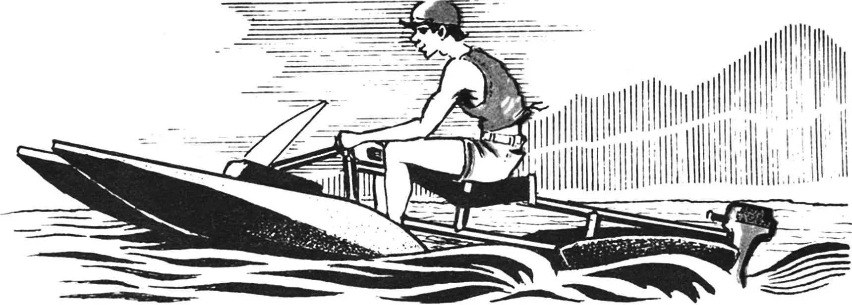
In the mid-80s, television screens in many countries widely advertised small, fast, exceptionally maneuverable motorized vessels under the general name “water motorcycle”: “jet ski”, “waterbot”, “hydrocycle”. They immediately won the hearts of water sports enthusiasts, displacing windsurfers, water skiers, and representatives of some types of water-motor sports.
However, reproducing a hydrocycle design at home is quite difficult due to high power requirements for the propeller-motor group of vessels (at least 35-40 hp) and the complexity of reproducing hydrodynamic surfaces. Those who are enthusiastic about this idea should turn to simpler designs. For example, familiarize yourself with the publication about the aquaroller in issue No. 6 of the “Modelist-Konstruktor” magazine for 1991. If for a number of reasons this scheme is not suitable, you can try to construct the machine proposed below. It consists of a frame, two pairs (front and rear) of floats, a front fairing, an engine, and a steering device.
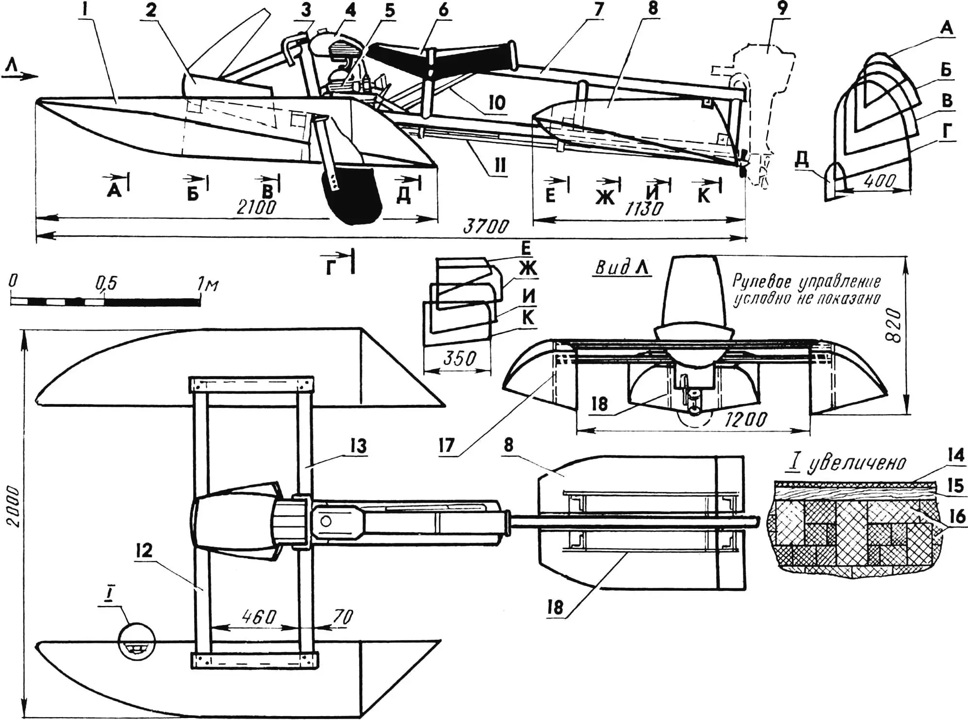
1 — front float, 2 — front fairing, 3 — steering device, 4 — fuel tank, 5 — engine, 6 — seat, 7 — frame, 8 — rear floats, 9 — outboard motor installation option, 10 — exhaust pipe, 11 — transmission shaft, 12, 13 — transverse beams, 14 — fiberglass coating, 15 — root float rib (plywood, s5…6), 16 — filler (foam blocks), 17, 18 — float mounting elements (plywood, s5…6).
The following materials will be needed: foam of any grade (preferably packaging foam), some plywood, old skis, several steel pipes, any motorcycle or moped engine, epoxy glue (3-4 liters), fiberglass (4-5 m2), tools and… patience.
On a flat surface (you can use the floor), you should draw the hydrocycle design in two projections (scale 1:1) and use them to preliminarily cut the material (pipes and foam).
Floats require special attention during manufacture. They are made from foam blocks, plywood root ribs, and mounting elements through sequential assembly-gluing. Then, using a hacksaw and sanding blocks, they are brought to the desired shape, covered with thin paper, and one or two layers of fiberglass impregnated with epoxy glue are applied (the bottom to the chines — in three to four layers). The floats are attached to the frame using transverse beams made from ordinary skis (we used semi-plastic ones) and reinforced with lower duralumin shelves. Such beams reduce impact loads during movement. If the strength is insufficient or the vessel is heavily loaded, they should be replaced with metal ones.
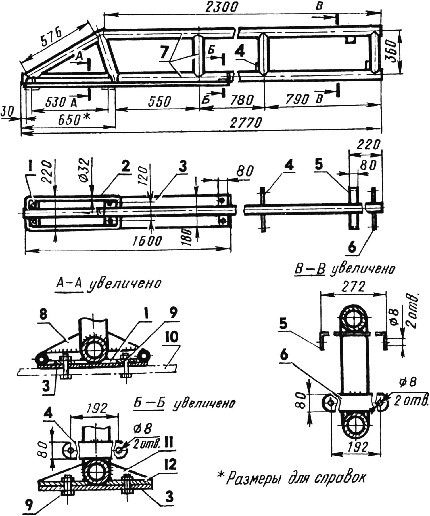
1 — overlays (St3, sheet, s3), 2 — front float mounting support (St3, pipe Ø32), 3 — footrest (D16T, sheet, s2.5), 4, 5, 6 — rear float mounting brackets (St3, sheet, s3), 7 — frame parts (steel 45, pipe Ø70), 8, 11 — gussets (St3, sheet, s3), 9 — M8 bolts (6 pcs.), 10 — rear transverse float mounting beam (shown conditionally), 12 — footrest mounting overlay (St3, sheet, s3).
The frame is welded from steel seamless pipes (Ø 70 mm) in a protective gas environment and reinforced with transverse gussets. If pipes of the required size are not available, you can use small-diameter pipes (30-40 mm), only in this case the power frame structure will have to be made spatial, which will somewhat complicate the work.
The steering device can be installed under the stern of the hydrocycle in the classic version, or, as we did, using bicycle parts — directly on the same shaft with the steering column, which is much simpler. However, this significantly increases the steering effort. The shape of the rudder blade outline is usually chosen to be close to a square. However, the device can also be controlled with the feet, similar to how it is done in speedway or road circuit racing on motorcycles.

1 — lower beam shelf (D16T, sheet, s2.2), 2 — upper beam shelf (ski), 3 — M4 screw, 4 — overlay (D16T, sheet, s2), 5 — bracket (D16T, angle 80x80x2.5), 6 — float reinforcement (plywood, s5…6).
The engine, which can be almost any (even from a starter, but with a power of no more than 18 hp), is mounted in the lower part of the frame near the driver’s feet. The propeller drive is through a shaft connected to the engine by a bevel gear. You can also use any other gears, it is only important that the propeller shaft rotates no faster than 3000 rpm. The fuel tank and other auxiliary engine elements will work from an old motorcycle or moped. Mounting units to the frame for various engines (for example, PD-8M, Sh-62) are selected on site, but at least at three points. The best solution would be to use elastic mounting through shock absorber blocks with rubber-metal pads.
The exhaust pipe is positioned based on convenience and safety, insulating it and securing it to the frame with clamps. Thermal insulation includes asbestos fabric, three to four layers of fiberglass mat, and a tin casing. But you can do it simpler and abandon the exhaust pipe if you arrange cooling of the exhaust pipeline with seawater. In addition, supplying water to the cooling jacket will significantly reduce the noise level, especially in two-stroke engines.
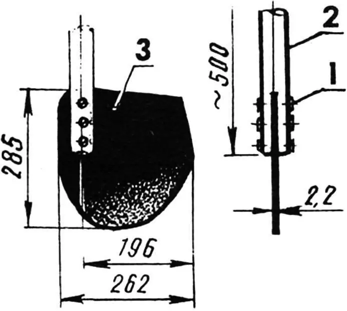
1 — M5 bolt, 2 — fork (D16, pipe Ø32), 3 — rudder blade (D16T, sheet, s2.2).
Standard boat motors such as “Veterok”, “Salut” are also suitable for the hydrocycle, it is only necessary to modify the stern part of the frame for engine mounting, using remote control.
However, if there is no engine, it’s not a problem; the hydrocycle design can easily be converted into a water bicycle, a sailing trimaran, or an iceboat, and the small weight (about 28-36 kgf) allows it to be easily transported by any means.
«Modelist-Konstruktor» No. 6’97, R. SINGATULIN
Recommend to read
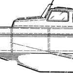 BOAT-PRAMOD
The problem of choice of the first model arises not only to beginners but to the heads of circles: what computers have to offer first came to class? After all, you need to choose one...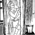 SHOWER, FOOT OPERATED
It is suitable for dachas and garden houses; can be used in field conditions. The design was approved by all who used it for several years. Usually summer shower is a box on the frame...
