In order not to reinvent the wheel, studied the relevant literature, are familiar with several versions of the development machines, but such that it would be possible to take a sample, have not met. Then, selecting from the collected information that I could use it, started to design its design. Having done the necessary study on paper and doing sketches of some parts and assemblies, began the manufacture of the machine.
Before starting to describe the design, I’ll tell you that the machine is comparatively small in size and simple in design and reliable and efficient in operation. It combines the advantages of branded machines:
— separate tables for sawing and planing ensure the execution of these works without readjustment of the machine;
— ability to set saw blade diameter up to 350 mm adjustment of cutting depth without any additional devices;
— change the depth of cut and high purity processing;
— collapsible design for transport or storage.
The lathe bed — prostranstvennoi (frame) design. Bearing racks (eight pieces) made of steel rod with a diameter of 18 mm, length 395 mm with thread M12 at the ends, and longitudinal beams (longerons) and cross (cross arms) — from a steel angle 50×50 mm. the joining parts of the frame, and the other nodes in the main screw, with spring washers. In such connections the machine can be easily disassembled for transportation or storage. In addition, the welding often leads to warping of the structure, so it was used only when absolutely necessary.
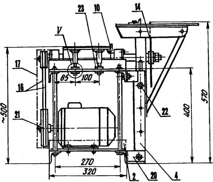
Machine Assembly (parts 1,2,4,6,7,20 made from a steel angle 50×50):
1, the lower spar (2 PCs); 2— tappet; 3 — support leg (steel rod d18 8 items); 4—guiding strut (L 395,2 PCs); 5 — lifting device of the table saw; 6 — upper bulkhead (L 800,2 PCs); 7—traverse (L 320,4 PCs); 8 — stand Desk plane (steel rod d18 8 PCs); 9— table of the planer (steel sheet 59, 2); 10—restrictive strap (steel angle 25×25, 350,2 L). 11—table saw; 12 — the bounding line; 13 — node driven shaft; 14—disc blades; 15 — bearing nut (8 PCs); 16—drive V-belt (L 1120,2 PCs); 17—a casing (steel sheet 51); 18 — the electric motor (3-phase, 2,2 kW, 1420 Rev/min); 19—under-motor plate (steel sheet s6); 20 — lower bracket (2 PCs.); 21 — drive pulley (d156); 22 — болтМ10 the locking of the lifting device; 23— adjusting and retaining nuts M16 spring washers (16 PCs.).
Table circular saw — solid steel plate with a thickness of 9 mm size 710×350 mm with a slot for the saw blade width of 10 mm. slot Length about 350 mm — maximum disc diameter, which can be installed in the machine.
From the bottom to the plate at a distance of 205 mm from the mid-privernuty bolts with countersunk head two cut corner 50×50 mm with a length slightly less than the width of the table. With their help, the console table is mounted on a rectangular frame of steel angle 45×45 mm, which can be moved up and down along the two additional rails of the uprights of the frame from the corner 50×50 mm. For this purpose, the side shelves of the vertical parts of the frame are made of the longitudinal slot dimensions 200×10 Mm, and the outer edges of these corners in order to snugly fit to the slide rounded on the inside radius of the struts (R = 5.5 mm).
For the mechanization of lifting-lowering of the table and a more accurate setting of cutting depth below frame of screw mounted lift fixed mortgage washers on the bolt from the corner 50×50 mm. Screw length 200 mm — steel rod with a diameter of 20 mm, it is threaded M20 until groove around screw head. Screw nut welded to the horizontal shelf of the bottom area of the frame. The outer ends of the consoles advanced reinforced area made of 25×25 mm struts. On top of the table, on the side of the slot for the saw blade, made of a plurality of pairs of threaded holes M8 for shifting and fixing the bounding line, are made from the corner 25×25 mm.
The table of the planer consists of two symmetric (with respect to the axis of the rotor plane) halves, made of sheet steel with a thickness of 9 mm. they are Mounted on the upper cross-beams (traverse) of the frame on opposite sides of the plane, each on four adjustable vertical supports, which in the body of the table represents the corresponding threaded holes M12. Support, as well as supporting the rack from a steel rod with a diameter of 18 mm. the Upper end of each support is made stepped. In the extreme stage is threaded M12, next to the M16, and it is pre-wound with round base nut. Thereafter, the end supports are screwed into the hole of the table, and the nut is fixed with a M4 screw. The threaded hole for the screw is in place after Assembly, at first in the nut and the plate of the table drilled hole of diameter 3.3 mm, then the hole in the nut reams to a diameter of 4.2 mm, and the plate tapped M4. At the lower ends of the supports threaded M16, which prior to mounting the table to the frame by a nut welling restrictive — it is intended for adjustment of the height and horizontal position of the table and consequently the depth of the planing. Another nut — fastener, it twists after the adjusting operations. On the right side (in the direction of movement of the blanks) on each side of the table, mounted and fixed from below with M4 screws limiters from a steel angle 25×25 mm. screw Holes are made on the above described technology of fixing the supporting nut.
Lifting device of the table saws (parts 1,3,6,7 made from a steel angle 50×50):
1 — the guide strut (2); 2 — movable frame (steel area 45×45); 3 — upper bracket (2 PCs); 4—table saw (steel sheet s9); 5 — the bounding line (steel angle 25×25); 6 — console; 7 — cross member; 8 — the screw M20 (steel rod d20); 9 — team washer (steel plate s 10,2 PCs); 10 — screw nut lift M20 (steel plate sl5); 11 — brace (angle iron 25×25, 2)
The most important site of the machine — driven shaft. It rotates in two ball bearing 180307 with dust seals installed in dismountable casings. The node mounted on the upper longerons of the frame in the middle of it.
The shaft is made as one unit with the rotor plane (the largest diameter). The rotor is made of three longitudinal profile groove, each of which with the help of clamping bars, and spacer M6 screws fixed knives of the planer. Three knives (usually two sets) to increase the productivity and the purity of the processed surface.
The shaft is made of steel 45. At one end is threaded M20. Here nut M20 between thrust and pressure profile washers fixed disc blades. At the other end of the shaft is made of a longitudinal keyway, and at the end of the axial threaded hole M8. This side shaft keyed planted double-strand driven pulley and fixed with a clamping screw M8 flat and spring washers. The rotation is transmitted to him by means of two V-belts length 1120 mm from the drive pulley of the drive.
Node output shaft:
1 — nut M8 spring washer; 2 — clamping steel washer 25x35x4; 3 — driven – pulley; 4— housing cover bearing (2 PCs); 5 — bearing 180307 (2); 6 — bearing housing (2); 7 — driven shaft (45 steel); 8 — resistant profile washer; 9 — a rotary blade; 10 — clamping profile washer; 11 — nut M20; 12 — clamping strip; 13 — knife planer (3). 14 — spacer screw M6 (6 PCs.)
As used in the drive three-phase motor power 2,2 kW with a speed of 1420 rpm. It is mounted on the metal plate 6 mm thick, in which are made longitudinal slots for bolts M8 for adjusting the tension of drive belts by moving the motor. The plate in turn is attached to the lower spars of the frame of the machine by the same bolts M8.
To ensure the shaft and, therefore, the planer and the saw the necessary momentum, the diameter of the driving pulley taken approximately twice larger than that of the slave. The machine is driven by enclosed protective metal housing.
V. AVTUKH, Grodno, Belarus
Recommend to read This legendary Emka Soviet passenger car GAZ M-1. The giant car plant in Nizhny Novgorod, was built in a record short time - just three and a half years. Creating it was a result of the signing of the 31... SHOES FOR THE STAIRS… There are many ways to keep a ladder from slipping. The easiest "put on" her old sneakers or shoes with a rubber sole.
Scroll back to top
 Woodworking machine in the personal sector never hurts, and in the construction or building a house or garden he is simply necessary. However, the ability to purchase it is not everyone. Moreover, commercially available machines also not all in all satisfied: the dimensions are large, then the possibility is too small, then again the price is high. With such a choice had to face me. Out of position is quite simple — estimated their capabilities and decided to make the machine: what I needed, especially since the motor and sortimenti metal I already had.