AN IMPROVED VERSION


IMPROVED VERSION
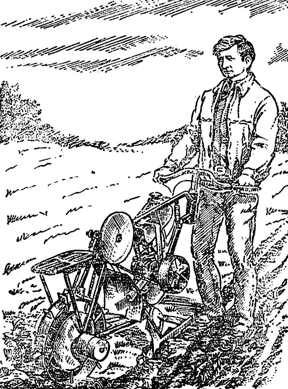
Isn’t it tempting to make a motor-plow design which has almost no welds! That’s why published in the “M-K” № 3, 1985 article “the wheel of veloplugs” on how to build such a mechanism using a frame end-of-century bike, had a great response.
However, many received letters contained requests to publish more detailed drawings, as well as to inform about the finalization of the engine. Today the author of the article “driving veloplugs” V. Zayets answers to these questions. At the same time we decided to acquaint our readers with one redeeming its simplicity Motovilova similar schemes, made students from the Novgorod region.
 
Operating experience of veloplugs, which I already told on the pages of the magazine, revealed some shortcomings in my initial design. So, to start the engine D-6 tow for one person was not possible due to the large transmission ratio of chain gear. The engine that did not have a forced cooling system, when working overheated. Due to the fact that the driven sprocket Z = 48 was near the wheel, the gap between them were filled with earth, as a result, the chain was loose. Not very well was installed the wheel, and its width was insufficient. Additional weight on the trunk of veloplugs necessary to improve the adhesion of the drive wheel with the ground, greatly increased the center of gravity and difficult to control. All this has forced me to take up the modernization of its mechanical assistant.
First of all, I have improved the frame — it extended 300 mm, and cut off the steering Bush welded on a corner lot. The width of the rudder increased, waru into it, insert a length of 250 mm. to provide a better grip of the drive wheel with the ground, made a new rim with a width of 100 mm, and this resulted in an increase in the distance between the feathers of the rear fork.
 
Fig. 1. Veloplus.
Fig. 1. Veloplus:
1 — engine, D-6, 2 — Bicycle frame, 3, 4 — covers, sprocket Z=48, 5 — idler sprocket bracket, 6 — a tension sprocket Z=10, 7 — bracket fan 8 — fan housing, 9 — fan, 10 — output sprocket Z=10, 11 — clip on the motor, 12 — tool (plow).
 
To the last on the right side of the frame attached to the kickstand from the bike — now veloplus not leans to the side when stopping.
 
Fig. 2. Frame.
Fig. 2. Frame:
1 — bushing steering 2 — additional longitudinal pipe 3 to the initial position of a sleeve steering, 4 — additional vertical tube, 5 — hole jet thrust fan, 6 — hole bracket-fan, 7 — hole bracket-idler sprocket, 8 — bushing the intermediate shaft (carriage), 9 — mounting bracket, drive wheel, 10 — bracket.
 
Fig. 3. Intermediate shaft.
 
The transmission is a two — stage chain transmission. The intermediate node of the transfer — carriage — consists of a shaft and two sprockets: Z = 48 from the bike and Z = 10 from the engine D-6. The shaft had to turn on the machine, but all the other elements of the carriage, including the bearings, used the finished, bike. The connecting rod from the sprocket Z = 48 cut off, leaving only the tail part with a hole for its fastening wedge. On both sides of the sprocket set cut from mm tin discs Ø 230 mm, which prevents a jump off the chain and shaft sprocket tightened nut M14. Another sprocket of the carriage — Z = 10 — fixed key.
 
As the power plant veloplugs I applied a simple and reliable engine D-6. Briefly talk about its revision. First of all it took to make the trigger. For this I removed the gear cover, unscrewed the M8 bolt and it is also found carved on the machine shaft pulley, tightening them gear Z = 20. To prevent accidental unscrewing of the shaft, I opal it around the sprocket. In the gear cover drilled center hole Ø 12.5 mm. by the Way, the starter pulley can grind aluminum, but you can take the ready — for example, electric motor washing machines “Riga”.
 
Not less important stage of refinement of the engine — taking out the output sprocket Z = 10 for the clutch cover. The very star I placed between specially machined flange and washer (see Fig. 4). Mount sprocket nut and lock nut and four screws M6. And head should opati or pour the thick paint, so they do not loosen due to vibration.
Fig. 4. The scheme of refinement of the engine.
Fig. 4. The scheme of refinement of the engine:
1 — engine, D-6, 2 — extension adjustment screw, 3 — clutch cable, 4 — release clutch lever, 5 — thrust washer 6 — pusher 7 — spacer flange, 8 — sprocket Z=10, 9 — a bracket clutch release lever, 10 — flange, 11 — shaft pulley 12, the starter pulley, 13 — Bush.
 
Fig. 5. Installation of the fan.
Fig. 5. Fan installation:
1 — area 40X40, 2 — bolt M8, 3 — frame veloplugs, 4 — arm movable pendants, 5 — movable bracket, 6 — hole thrust 7 bushing fan shaft, 8 — shaft of the fan 9 — fan, 10 — sprocket Z=10.
 
Fig. 6. Bracket idler sprocket.
Fig. 6. Bracket idler sprocket:
1 — tube frame, 2 area 30X30X3, 3 — bolt M8 4 — area 25X25X3, 5 slot for adjusting the tension of the chain.
 
Fig. 7. Shaft idler sprocket.
This alteration was made to change the schema of the clutch. I had to pull release the clutch lever and the center position of the pusher in the lid to drill a hole of Ø 20 mm. In the clutch cover over the location of the shaft clutch release lever drilled hole Ø 10 mm and cut it, thread M12. Then machined a bolt extender, which is placed on top of the adjusting bolt clutch cable. To the lower opening of the cover is attached a bracket clutch release lever clutch. The lever is made of steel rod Ø 8 mm length 215 mm. In the hole in the flange of the drive sprocket placed the ball and put a pusher with a length of 85 mm, after which the bolt is attached M4 release lever to the bracket and installed the clutch cable. Diagram of the modified engine is shown in figure 4.
 
In working condition veloplugs moves at a speed of 4.1 km/h. Naturally, the D-6 engine in this mode of operation greatly overheated. So I had to make a forced cooling system. Fan cut out of tin with a thickness of 1.2 mm, its lobes are bent at an angle of 30°, the drive from sprocket Z = 10, which engages with chain adjustable plate bracket (see figure 5). The blades rotate in the casing of tin, Ø 190 mm.
 
V. ZAYETS, Kharkov

Recommend to read

  • AND AGAIN THE MOTORAND AGAIN THE MOTOR
    To drive in many modern pneumatic machines and tools required compressed air pressure of 3-4 ATM. Is it possible to build a mechanism which effectively would have used a pressure...
  • DOSIMETER RIDERDOSIMETER RIDER
    For reliable operation the two-stroke engine is a very important proportion of oil content in gasoline. In order to accurately observe it, make a simple dosimeter. On the high...