SPRING A BLUEPRINT

SPRING A BLUEPRINT
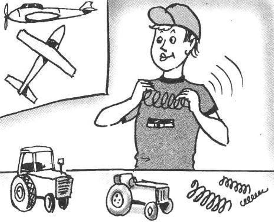
Currently in stores you can easily buy any necessary household products. At the same time, attention and creative efforts of Amateur designers more going on technically complex objects: tractors, ATVs, cars and even airplanes. Changing the homebrew approach to the implementation of the projects; they are not afraid of the need for self-production of complex and accurate parts, which moreover may be subject to strict requirements in terms of strength. One such typical elements present in almost all energy-intensive structures, are cylindrical helical extension springs or compression. In this regard, many of our readers will be interested and, hopefully, it is useful to get acquainted with the methodology developed by the Ukrainian engineer Vladimir Vinichenko, which will help the responsible production of springs with the required quality and accuracy.


The proposed method for winding helical coil springs implemented on screw-cutting lathe with a special fixture consisting of bars and copier. In a machine tool cartridge is attached to the mandrel with the hook in the view holes in end flange for fixing the beginning of spring wire. In the blade holder install the holder with the copier. Copier is the shaft with the cut spiral groove variable pitch, which freely rotates in two bearings. Grooves at the beginning and at the end of the copier, ensure the winding turns of pre-loaded springs, and the Central part — the winding work of the coils with the desired pitch and diameter.
Holder copier is a structure made out of 40 mm steel plate, reinforced edge 10-mm band, and two bearing housings. The right body is welded to the plate, and the left bolts M12 (to enable replacement of the copier). Specific drawings for the tool holder are not submitted because they are dictated by the type of screw-cutting lathe and the size of the wound spring. Manufacturer of springs made in the following sequence. First blank — dimensional length of wire bent at 90° with the end of a length of 4 — 5 d is omitted from underneath the copier and installed in the hole, the hook of the mandrel. Then, the copier is rotated manually to align the start groove with the position of the wire. Her tightness and continuous contact with the helical groove of the copier provided with significant bending strength spring steel of the workpiece. The process of formation of spring starts turning on the machine spindle at minimum speed. The circumferential wire on the mandrel, and the step is set spiral groove rotating in bearings of a copier.
 
Scheme of winding and helical springs using the copier
 
Scheme of windings and helical springs using the copier:
 
1 —mandrel; 2—removable bearing housing; 3—wire; 4—rib reinforcement; 5—plate; 6—escargotel screw-cutting lathe; 7—welded to the bearing housing; 8 copy; 9—three-jaw Chuck

 
The following is a method of calculating the parameters of the mandrel and copier, providing the necessary dimensions of the spring.
 
Legend in the calculations.
 
The original data (the size of the springs):
 
n — the number of working coils;
 
n1 is the total number of turns;
 
t — step of the working part;
 
Do — inside diameter;
 
D. — the average diameter.
 
The parameters of the copier:
 
l — length of the working part;
 
DCOP. — inner diameter groove;
 
Dnl. the diameter of the neutral line of coils are wound on the mandrel;
 
k = Dnl./DCOP. — correction factor;
 
T — step helical line of the working part;
 
Tn — step spiral lines of the input and output parts.
Mandrel:
 
dODA. is the diameter.
 
Intermediate calculated values:
 
L is the length of one coil spring without taking a step;
 
DMs. ODA. — the average diameter of the spring windings wound on the mandrel;
 
X — factor table to determine the neutral line in bending;
 
β — coefficient taking into account the spring properties of the wire;
 
nODA. — the number of working turns of the spring are wound on the mandrel, taking into account the elasticity of the wire;
 
L1 —length of wire passing through the working part of the copier;
 
L2 is the length of the wire working spring windings wound on the mandrel;
 
L3 is the length of the wire wound on the mandrel with the accounting of pre-loaded coils;
 
L4 is the length of the wire spring according to the drawing.
 
Crucial in the calculation has a value that takes into account the elasticity of the wire when bending. It is used in determining the mandrel diameter and number of turns of SOCA. To determine the value of this quantity the following procedure is recommended. In the first approximation is made mandrel of diameter Don. On CNC turning machine mandrel in a circumferential 5 — 10 turns of wire with a step of approximately equal to the pitch of the spring. The tool post equipped with special roller with a groove. After coiling is determined by the angle of unwinding all of the spring windings ą, we compute the angle per one revolution and in conclusion — coefficient = ą1/360°/ taking into account the elasticity of the wire of the given material.
 
Parameters of the mandrel and wire
 
The parameters of the mandrel and wire
 
The copier, ensure the winding of the springs with working windings in the center and tucked — in the beginning and at the end of the spring
 
The copier, ensure the winding of the springs with working windings in the center and tucked in early and late spring:
 
1—the Central part of the copier working winding of the coils; 2 — the end part of the copier machine for winding pre-loaded coils; 3 — pin 08 (4 PCs); 4—screw M8 (4 PCs)

 
The following is the method on the example of calculation of the size of the copier and mandrel for coiling spring steel 60S2A-IN-1-HN GOST 14963-78 with the following parameters: n = 9; n1 = 11; t= 14 mm; Do = 42 ± 0.9 mm; d = 8 mm; D. =50 mm.
 
For the given size of a spring by the above procedure is experimentally found increase of arc of one revolution of 30° after removal from the mandrel with a diameter of 42 mm, which corresponds to an increase of the length of the loop in 1,083 times (β = 30° 360° = 0,083). On this basis,
 
DMs. ODA. = (L – βL)/ π = L (1 — β)/π = 157×0,917/3,14 = 46 mm,
 
where L = π D. = 3,14×50 = 157 mm;
 
dODA. = DMs. ODA. — d = 46 — 8 = 38 mm
 
nODA. = 1,083 n + 0,25 = 1,083 + 0,25= ~10,
 
where 0,25 is an incremental part of a revolution taking account of the tolerance in the number of working turns.
 
The diameter of the neutral line of the coil on the mandrel (Fig. 2) calculated by the formula:
 
Dnl. = dODA. + 2dX.
 
X is determined by the table [1] depending on the ratio of dODA./2d (in our case 38/ (2×8) = 2,375)
 
Interpolated and calculated X = 0,458, rounded to 0.46.
 
Then Dнл = 45,36 mm.
 
Dкоп in the first approximation is taken equal to Don = 42 mm.
 
Then the ratio k = DIl./DCOP. = 45,36/42= 1.08 zone.
 
Length of the working part copier: = t·n = 14×9 = 126 mm.
The calculated step of the working of the copier:
 
T = l/(nODA. k) = 126/(10×1,08) = 11,67 mm.
 
The calculated step of the working of the copier is rounded to the nearest step feed screw-cutting lathe (T = 12 mm) to provide the possibility of cutting spiral grooves. To maintain the specified step of the spring the inner diameter of the grooves of the copier is recalculated from the condition of the selected step of the copier:
 
k = l/(T nODA.) = 126/(12×10) = 1,05.
 
Then DCOP. = Dnl./K = 45,36/1,05 = 43,2 mm.
 
The number of turns of the input and output parts of the copier is selected equal to 1.5. Step grooves of these parts is determined by the experimentally established formula:
 
T = 0,875 d = 0,875×8 = 7 mm, equal to the nearest step of feeding the machine (7 mm).
 
The lead-in and outlet side welded to the axis of the copier, or are attached two pins with a diameter of 8 mm and two screws M8. A pair of lead-in grooves and output parts of the copier with a groove of the working part is handled manually with a file, providing a smooth transition. Material copier — 45 steel, heat treatment — hardening to a hardness of HRC38…42.
 
 
For verification of the calculations is determined by the length of the wire:
 
L1 = DCOP π 1/T = 43,2×3,14×126/12 = 1425 mm
 
and compared with the length of the wire:
 
L2 = Dnl. π nDef. = 45,36×3,14×10 = 1425 mm.
 
Also, compared to the length of the wire:
 
L3 = Dnl. π (n, ODA. + 2×1,083) = 45,36×3,14(10+2×1,083) = 1733 mm length of wire:
 
L4 = (Do +2d X) π n = (42 + 2x8x0,46) XS,14×11 = 1705 mm.
 
With proper calculation error of λ should not exceed 2.5%. In our case:
 
λ = (L3 — L4) 100%/L4 = (1733 — 1705)100/1705= 1,6%.
 
V. VINICHENKO, Mirgorod

Recommend to read

  • EXTENSION OF… BUTTONSEXTENSION OF… BUTTONS
    One has only to afford some indulgences — and now you're does not add up — even buy a new, bigger size. However, there is a way for a while, until you go back to the old weight. Take any...
  • THE MIRACLE STOVETHE MIRACLE STOVE
    In one of the spring gear of the Central television can be enthusiasts of technical creativity familiarized with the universal camp stove, or rather, a kitchen that has designed and...