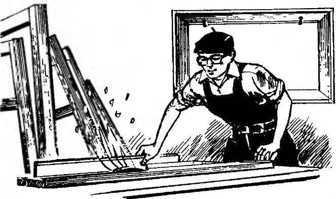
In a makeshift planer front Desk with adjustable height work surface allows to provide the desired chip thickness. And this is the quality and processing performance. In this design of machine front table is raised or lowered in an inclined guide for moving by means of the lead screw.
This feature of the machine lies in the design of the frame, which consists of symmetrical halves, welded steel corners and United othertown-tion on a lathe four pipes. The height of the frame in the figure corresponds to the Board version of the machine, with its outdoor performance, this size should be such that the working surface of the rear table was at a height of about 800 mm.
In the upper surfaces of the frame are made grooves and holes for fastening the bearing housing knife shaft.
Installation guide front table included weld to the frame base plate and two side plates (all details of steel sheet with a thickness of 9 mm) and the base screw and two linings.
Side plates welded in the presence of the guide plate in front of the table with spacers to ensure the clearance of its free movement in the future. Bearing lead screw on the base plate and the nut on the front table welded Assembly with a screw.
Table surface planer:
1 — frame; 2 — front Desk; 3 — the bearing housing knife shaft; 4 — pin M8 (4 PCs); 5 — rear of table plate (steel, sheet 350x270x9); 6 — base support screw; 7 — screw bearing cover; 8 — plate (steel, sheet 190x45x3); 9 — side plank (steel, sheet 190x34x9); 10 — base plate (steel, sheet 260х 190×9); 11 — lining (steel, sheet 190x30x1); 12 — screw moving the front of the table; 13 — M10 screw (6 pieces)
Bed:
1,5 — supporting brackets (corner 50x50x5); 2,4 — frame (corner 50x50x5); 3 — spacer (pipe 25×2, 4 PCs.)
Front Desk:
1 — top plate (steel, sheet 300x270x9); 2 — guide plate (steel, sheet 192x45x9); 3 — side panel (steel sheet 190х 110×9, 2); 4 — sliding nut M16
The front Desk consists of an upper and of the guide plates are joined by two sidewalls. The short side plate strictly parallel to each other and are well treated. Sidewall received by the processing circuit of the two stacked together work pieces. In the same folded form in the sidewalls of the drilled holes with a diameter of 8 mm under temporary pins required for Assembly (welding) of the front Desk. After welding of the sidewalls with the upper and the rail plates mounting studs were removed.
A few words about the setup of the knife roller. The machine design allows to use the blade shaft planing width 200 and the diameter of the cutting part of 80-110 mm.
The shaft Assembly with the bearing installed in place with some advanced actions. The front table raised to the level of the cutter shaft and with the help of spacers aligned so that the beveled edge of the table and the shaft axis are parallel. After that, the frame is marked and drilled holes for mounting of supports of the knife roller.
Fixed rear machine table adapted in height and placed parallel to the knife shaft by means of four M16 studs. To do this, cut four in the bed groove and in the rear of the table plate drilled four holes for the threaded heads of the studs. The corresponding rotating nut and moving the studs in the grooves, it is possible to provide the necessary clearance between edge of rear table and cutter block.
C. TULUMJIAN, s. Sadovoe, Republic of Kalmykia
Recommend to read SHREDDER FEED Wags say that invention, they say, are born from laziness. Maybe they're right. I tired to cut the tops and chop the root vegetables for domestic animals manually — set about creating an... FRIGATES AND CORVETTES Not to say that after the First world war, the British did not think about the problems of a future war, but their reasonable ideas are embodied in a metal surprisingly slowly. For... 

