TABLE UNIVERSAL

UNIVERSAL TABLEIn one of the shows can viewers was submitted to design a universal machine, designed by the engraver of the suburban town of Troitsk Y. M. Orlov. Not only a discussion of a design program participants, but also by the numerous letters received by the author, editions, TV and the magazine “M-K” showed how great the interest was this table versatile machine capable of performing a number of operations for machining a variety of materials. To meet numerous requests, the editors asked the author designs to tell more about it.

It is known that many machines, the tool performs rotational motion about the details, and they differ from each other primarily only horizontal or vertical arrangement of the working body, as well as the use of additional equipment and fixtures. This led to the idea of using for different operations of a single power node consisting of a caliper with a fortified it the spindle head and the motor connected by a belt. And in order that the spindle could take the horizontal and vertical position — make the whole site turning! This idea was implemented. For skills on lathe and milling machines manufacturer of universal difficulties is not present.

 
On the basis of rectangular duralumin sheet 25Х400Х500 mm — two racks are mounted cylindrical steel rods of Ø 38 mm. They are connected at the level of the base and at the top of two bridges made from a steel strip with a thickness of 25 mm.
The slide caliper spindle head — milled brass block sizes 75X100X160 mm.
 
Although the massiveness of these parts leads to increased complexity of manufacturing, their rigidity depends on the future accuracy of the machine.
 
In order for the caliper had the opportunity to move along the rack, its slider reinforced lead screw nut, and the screw — a steel rod with M20 thread — installed between racks in the upper and lower bridges and the rotation of the flywheel has the ability to turn in the bearing Assembly of the lower bridge and brass plain bearing — Limbe — top.
 
Fig. 1. The machine in horizontal version
 
Fig. 1. The machine is in a horizontal version:
 
1 — spindle Assembly 2 — fastening flange of lathe chucks, 3 — lathe chucks, 4 — mandrel for installing saw blade, 5 — reference table, 6 saw.

 
Fig. 2. Vertical version of the machine
 
Fig. 2. Vertical version of the machine
 
Fig. 2. Vertical version of the machine:
 
1 — flywheel with handle, 2 — limb-bearing, 3 — upper bridge, 4 — screw vertical feed (M20), 5-nut caliper with a split flange, 6 — slide caliper spindle unit, 7 — turret, 8 — pulley spindle, 9 — locking nuts, 10 — masloudalyayushchie ring 11 — bearing No. 205, 12 — spindle 13 — housing 14 — axial bolt fixing the rotary support 15 — additional bolt 16 cover bearing 17 — bearing No. 202 18 — the thrust bearing № 8102, 19 — washer 20 — nut 21 — the lower bridge 22 base machine, 23 — screw-stem.

 
To compensate for possible axial clearance in the threaded connection in the flange nuts caliper is provided a groove drawing in which it is easy to reduce the gap. The shank of screw nuts fastened in the bottom of the bridge via two bearings: radial No. 202 and resistant No. 8102. The” Kai design ensures free rotation of the screw when the possibility of a complete sample of an axial clearance.
 
The mechanism of the vertical feed allows you to accurately determine the movement of the slide, guided by the angular rotation of the lead screw. On the conical surface of the limb-bearing suffered a series of uniformly distributed around the circumference of the grooves. The price of division of the limb obtained by dividing the pitch lead screws on their number.
 
Of great importance for the accuracy of the machine is free, but besluttede the movement of the slide along the guide rails. It depends, first, on the accuracy of the aging center distance of the holes of the strut in three parts: the slider, the upper and lower bridges and, second, providing gapless pairing: rack — slide. The first condition is easily ensured by the joint handling of these parts during manufacture, and the second to fit the outer diameter of the uprights to the diameter of the holes in the slide.
 
Power node of the machine consists of a rotary caliper, spindle head and plate fixation of the motor. The entire Assembly is mounted on the slider is able to rotate around a horizontal axis to any angle and secured in selected position by means of an additional Central bolt.
 
To make a turret from a round steel rod with Ø 100 mm and length 170 mm, profiteroles in its cylindrical surface a radial groove for installation of the bearing plates of the motor and two parallel platforms — for ring clamp spindle Assembly.
 
The motor is mounted on the bracket by two steel plates bolted through the grooves, providing the possibility of adjusting its position. This gives you the opportunity to set the pulleys of the motor and the spindle in the same plane and to provide the necessary tension on the timing belt.
The spindle head is composed of parts, easily machined on a lathe: housing, spindle, melodiewinawer rings, clamping nut and multi-strand pulley.
 
The spindle is hollow steel shaft is revolved by electric motor through V-belt transmission by means mounted on the keyway on the pulley. The working shank of the spindle has an internal taper overschie under No. 2, and the outer diameter of the thread RESPECTED. This gives you the ability to set the tool with an ionic shank drill bits, reamers, core drills, boring heads, collets, drill chucks, and with the adapter flange and rim — lathe chucks, faceplate, grinding wheel, polishing wheels, ceramic cutting disk cutter the saw.
 
Of course, the most effective use of these tools will require some adaptations. Thus, when the vertical orientation of the spindle for performing drilling operations it is desirable to use machining vise. When drilling small parts it is more convenient to use a Desk lever or gear type.
 
Greatly expand the functionality of the machine application of the coordinate table with a fortified it by the machine vise. Due to the presence of two mutually perpendicular to the lead screw of the part, clamped in a Vice, it will be possible to shift relatively to the rotary tool in two directions (in two coordinates). This will allow for vertical layout to perform milling, and horizontal, holding the item in the Chuck, and the cutter — vise — lathe. To sharpen details of considerable length and to process solid materials: steel, cast iron, bronze, on the table you can fasten the tailstock, and the caliper to be equipped with additional sliding bar, fastened at the base.
 
Fig. 3. Power host machine
 
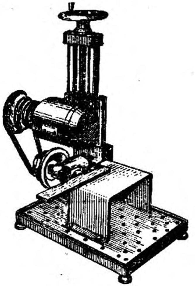
Fig. 3. Power host machine:
 
1 — a pulley of the motor, 2 — motor N — 180 W, n = 1380 rpm, 3 — plate engine mounts, 4 — base plate bracket, 5 — V belt, 6 — a pulley of the spindle.

 
Fig. 4. A set of basic tools to the machine-wagon
 
Fig. 4. A set of basic tools to the machine-universal:
 
1 — collet draw bolt, 2 — tool taper shank, 3 — setting tool through the transition cone, 4 — drill Chuck on a tapered mandrel, 5 — the Chuck with the transition flange, 6 — disc mill, 7-10 tools with cylindrical shank: drill bit, core drills, reamers, boring heads, etc., 11 is a mandrel for mounting sanding, wire, buffing wheels, 12 — cylindrical mandrel for pressing.

 
To turn the machine in a circular saw, you can use simple U-shaped table, bent from steel or dural sheet with a thickness of 2 mm.
 
various household mechanisms: engraving installation, mixer, winding machine, spinning wheel and even to help the hostess — the grinder and the shredder!
 
The base of the machine with vertical feed mechanism can perform another “moonlighting”: when replacing a spindle head, a simple cylindrical mandrel turns out powerful enough press, which is useful in Assembly operations, and the bonding and vulcanization.
 
Noi is not limited to this list of capabilities of the machine. Simple devices allow to produce it armored mesh, to carry out rolling through the simple and contoured rollers or replacing rollers on circular blades — slitting sheet materials.
 
In addition, on the basis of this machine is designed and tested in the original design pantografos copy of the installation, ensuring microreserve any profiles, inscriptions and images on the copier with a scale reduction from 1 :1 to 1 :50!
 
Y. ORLOV, R. MAY, Troitsk, Moscow region

Recommend to read

  • NEEDLE VS ICENEEDLE VS ICE
    Using a wheelchair with a stick, faced with the problem of movement in ice. After several trials, it was decided to streamline the stick. In its bottom I drilled a series of blind holes...
  • ON THE TRACK, “LENINGRAD-2”ON THE TRACK, “LENINGRAD-2”
    Several years ago I came across a photograph of an unfamiliar race car. Machine interested, but no additional information about the photo caption does not contain, and the search for...