 When my family moved to is not a new manor house with land, I faced the problem of its thorough repair and erection of outbuildings. It was clear that with only hand tools this kind of work will not do. And therefore decided before you start construction, along with concrete mixer, to make at least a simple woodworking sawing-planing machine, called artisans “circular saw”.
A General idea about the design of these machines, of course, had seen industrial designs in the shops, met and improvised (the latter not worse). But before the production of the reviewed articles on this topic in the journals, in which the craftsmen described their original design.
The manufacture of the machine started with the purchase of the rotor shaft or, more precisely, — three-knife planer with bearings and casings. He completed a double-sided knives, and with a spare set. Himself the site conditions of a home workshop (even with lathe and milling machines) to manufacture is not easy. In addition, require good balance in the collection, which can only be performed on a special stand (in any home workshop it’s not), or on the finished machine, which still needs to be done.
Machine design, we can say, classic, but without the original decision has not done. But this — the course of the story.
The frame of the machine — four. It is based on four legs, made of channel number 8 thrust bearing to increase the area of support. At the top of the legs are connected by longitudinal and transverse bracing. The first is made of steel angle corner 70×70 mm, and the second from a similar area of 63×63 mm.
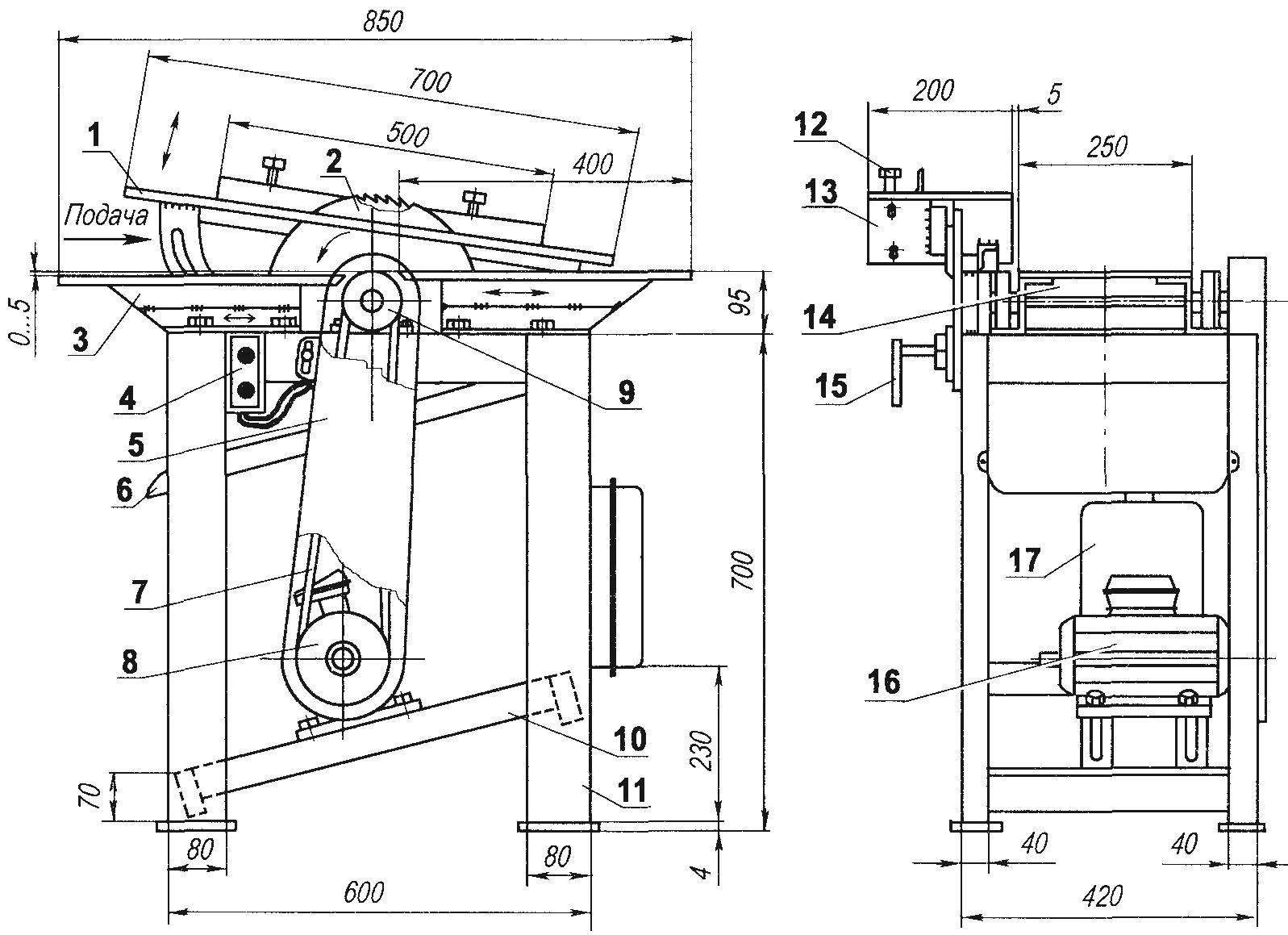
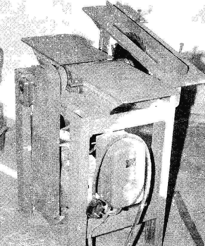
Raspilovochnyj wood cutting machine:
1 —table saw; 2 — circular saw (Ø400); 3 — table of the jointer left, right—mirror; 4—electric starter; 5 — shroud, 6 — tray for removal of sawdust and shavings; 7 — drive belt; 8 —drive pulley V-belt transmission; 9 — driven pulley belt transmission; 10 — the bearing of the electric motor; 11 — frame of the machine; 12 — guide-line; 13 — joint lifting of the saw table; 14 — rotary shaft; 15 — a clamp for fixing the saw table in a raised position; 16 — motor (U = 380 V, n=3000 rpm N=3 kW); 17—electric switchboard
In this longitudinal ties are the supports for the rotary shaft of the jointer, as well as receiving and infeed planer table. Immediately, I note that the outfeed table is mounted flush with the exposed blade of the knife (through washers or plates), and the infeed table is below this level at a depth of cut.
At the bottom you feet touch the transverse and longitudinal supports of the motor. In the latter made the slots, and they are mounted at an angle. Moving them to the motor to adjust the tension of the driving V-belts.
Double-strand pulleys picked up ready — from a decommissioned farm equipment. But I want to say that with such power of the motor (3 kW) and the number of revolutions of about 3000 per minute of two straps a little too tight they have to pull.
Returning to the planer tables (giving and receiving), note that by design, they thermalneutron. Cargame for them are Z-shaped profiles, welded of two pieces of angle corners 40×40 mm.
To the upper shelves of a pair of rings welded to the plate table and the bottom shelves are made of longitudinal grooves for attaching them to the frame longitudinal relations by bolts M10. It is possible, instead of grooves in the shelves to fulfil and the corresponding holes, just drill them together in cargo tables and longitudinal connections of the frame during Assembly of the machine, the pre-adjusted position of the tables relative to the plane.
Sawing table at first glance also seems to be normal. But it has a unique adjustment mechanism of its lifting-lowering to set depth of cut. This operation is carried out by otverdevaya and subsequent tightening of a single clamping — bolt M12, which I also supplied with a toggle and at the same cost even without the keys.
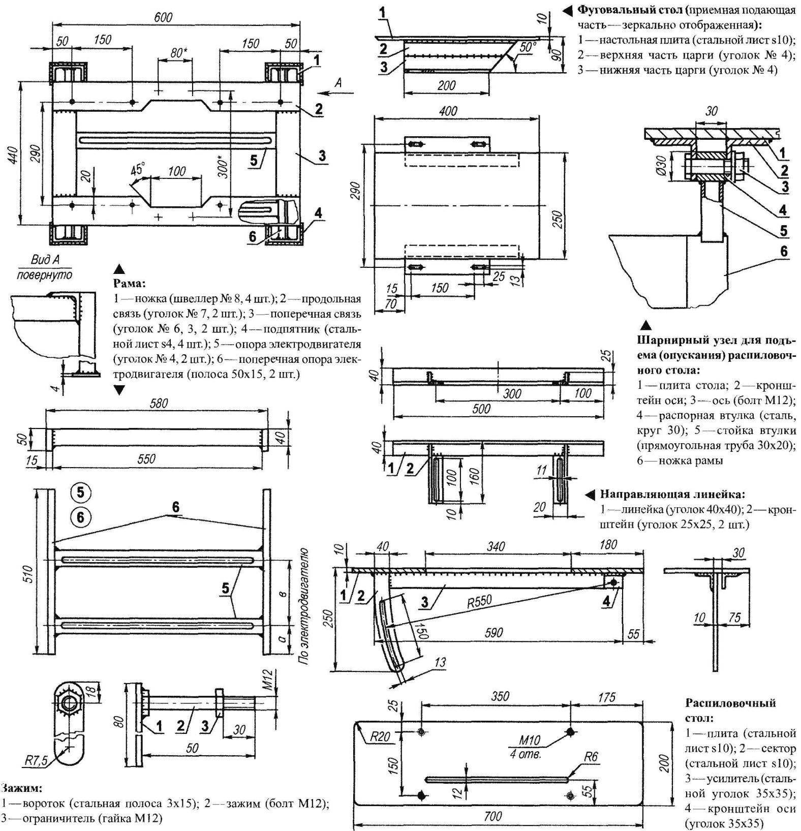
Sawing the table is a plate made of steel 10 mm sheet. The bottom is welded to the plate amp from a steel angle 35×35 mm. With one end of the amplifier to him and to the plate welded to the sector of the lift adjustment of the table, and around the other end bracket from the same area. In both parts together made the holes for mounting the axis of the sawing table to the frame. Axis M12 bolt inserted into the sleeve of the rack welded to the frame. Sawing table provided with adjustable slide for workpieces made of angle area of 40×40 mm.
In conclusion, under the shaft of the planer is mounted a tray of thin steel or dural sheet to collect sawdust and shavings. Pan tilt in any direction.
The conventional wiring for 3-phase motor — it is repeatedly cited in the journal “modelist-Konstruktor” and repeat her no need. I will remind only that switch should be easily accessible. Drive is also necessary to close the cover and strictly observe safety precautions when working on the machine.
A. MATVEICHUK, Zavodoukovsk, Tyumen region.
Recommend to read
 THROUGH THE BAR
It is not easy to drill pipe, clamped it in a vise and nukernel. The task will be made easier if you resort to using a small block of wood. It is administered in the Vice with the tube... UMBRELLA ON WHEELS
When there is no permanent gazebo on a summer cottage for rest on a hot summer day, the only salvation from the scorching sun is a large "beach" umbrella. The undeniable advantage is that...
