 Many hobbyists and tinkerers have a tabletop lathe woodworking machine STD-120 and its modifications. There are machines and in school workshops. The presence of such equipment allows like young homebrew, and podnatorel handyman to create wood original, beautiful machined parts decorative and utilitarian purposes.
According to the passport data the machine is designed for processing blanks up to a length of 450 mm and a diameter up to 240 mm. in practice, However, it is necessary to produce parts with large dimensions (for example, balusters for stairs, table legs, decorative plates, dishes, etc.).
And then the capabilities of the machine for the realization of ideas is not enough, and the problem of modernization of equipment.
To this end, I made a number of changes to the structure of the machine, which was able to handle the part twice as long or twice the diameter.
The modernization of the equipment in the school workshop was conducted in two ways.
Work on the first version of transformation began with that disconnected the wooden base from the supports of the machine and took off the factory rack, extended it 600 mm (although it would be possible to produce and new whole), leaving the width and thickness unchanged. Of the base docked with a plywood tenon on glue, fluff them, and the ends of the boards. For a more reliable joining of the parts of the base to the sole at the edges on the entire length (1850 mm) glued and privernuli screws bruski section 50×20 mm.

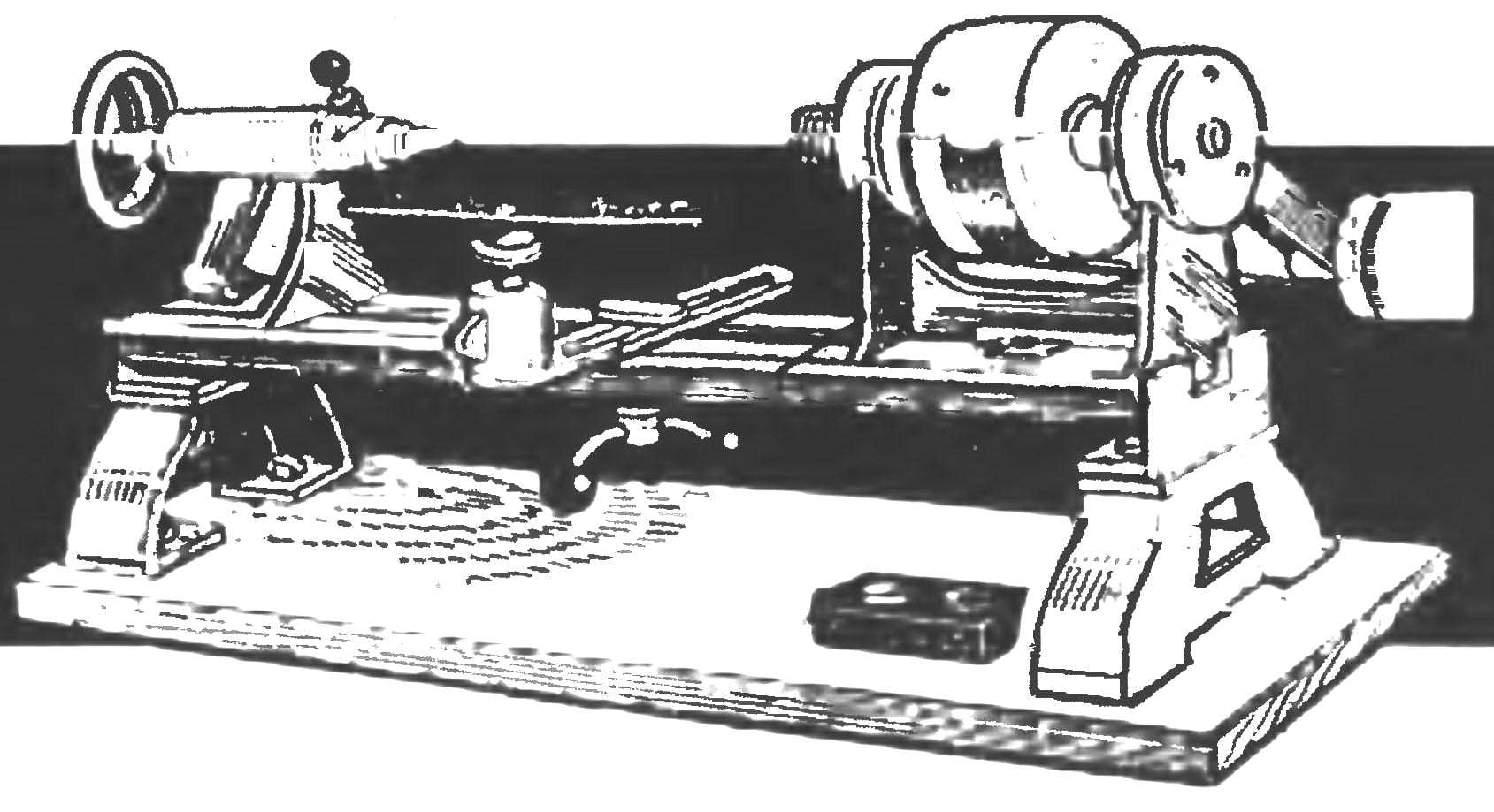
Lathe woodworking machine STD-120:
1 — base; 2 — track (2 pieces); 3 — motor (electric or an electric drill); 4 — headstock with the spindle; 5 — tailstock with center; 6 — armrest; 7 — a support (2); 8 — remote control

The first option is the modernization of the machine (with one machine):
1 — the left part of the machine; 2 — the right side of the machine; 3 —sub-part of the Foundation (Board section as the main part); 4 — longitudinal connection (bar 50×20, 2); 5 — tongue (plywood, s7); 6 — pin M12 (2pcs); 7 — additional support (wooden block); 8 — damping bearing (rubber s5, 6 PCs.)
Even from the bottom to the bars to dampen vibration attached six rubber shock absorbers 50x50x5 mm (at the corners and two in the junction parts of the base).
Then sawed in two guides of the machine (at a distance of 15 mm to the left of the spindle nose, dropping him from a perpendicular to the guides).
The left part of the machine with headstock mounted on a former place, securing one end (left) on regular support. Under the right end of this part framed with additional improvised wooden prop, gluing her soles to the base and securing in the middle of a long pin M12 length 170 mm.
The right side of the machine (tailstock) pushed almost to the opposite end of the elongated base and fixed it here is exactly the same as the left part: one end (rear) on regular support, and the other (front) on a homemade wooden stand. But before fixing carefully checked the relative position of the two parts: below the guides are on the same line, and therefore centers on the same axis since Otherwise considerable runout of workpieces during their processing.
The second version of the modernization carried out using another machine STD-120 (let it be even faulty, just to be a guide but at least a prop).
The base of the machine is extended just as it was described earlier (or taken whole).

The second variant of modernization of the machine (if you have two machines):
1 — the first machine; 2 — cut off the right part of the second machine (turned 180°); 3 — additional support (wooden block 200×80); 4 — pin M12; 5 —additional part of the Foundation (Board section as the main part); 6 — shock-absorbing bearing (rubber s5, 6 PCs); 7 — longitudinal connection (bar 50×20,2); 8 — tongue (plywood s7)

The handrest:
1 — console (steel sheet s10, 2); 2 — strut (steel, circle 24, 2); 3 — clip (steel, sheet s3. 2); 4 — emphasis (a wooden rail section 120×20)

The maximum dimensions of workpieces that can be machined:
and demodernisation; b — on a modernized according to the first embodiment; the upgraded according to the second embodiment
Rails (frame) are cut only on one machine and it uses only the right part, along with staff support. However, she (right side) rotated 180° and supports both machines through existing holes in them tightening the bolts M8. Docked right ends of the guides are mounted on the support, taken from beneath the headstock on the second machine (being made new according to the above for the first variant of modernization of the machine diagram).
Adjustment of machine setting and guides the alignment of the centers of the front and rear grandmas — is the same as in the first variant of modernization.
For the upgraded machine both the first and the second variant may require a different armrest. You can do it yourself. Console new armrest are similar but longer. Replace the height Adjuster on both sides of the armrest installed racks with the braces, instead of focus — a long wooden plank. Strap height (and hence the fulcrum of the tool) is regulated by several pairs of locating holes drilled at its ends. Console new armrest not attached to the guide frame and to the wooden base with bolts M12.
In the processing of short workpieces with a large diameter (for example, in the manufacture of cups, trays, etc.) staff the handrest is mounted across the guides.
Material and time costs for rework machine a minor, after upgrading are almost the same as the fixed outdoor bench.
If this alteration of the machine will interest and will be used by someone of the readers, the author will consider his task fulfilled.
V. PUSHKIN, lecturer of labor studies, Kaluga


