
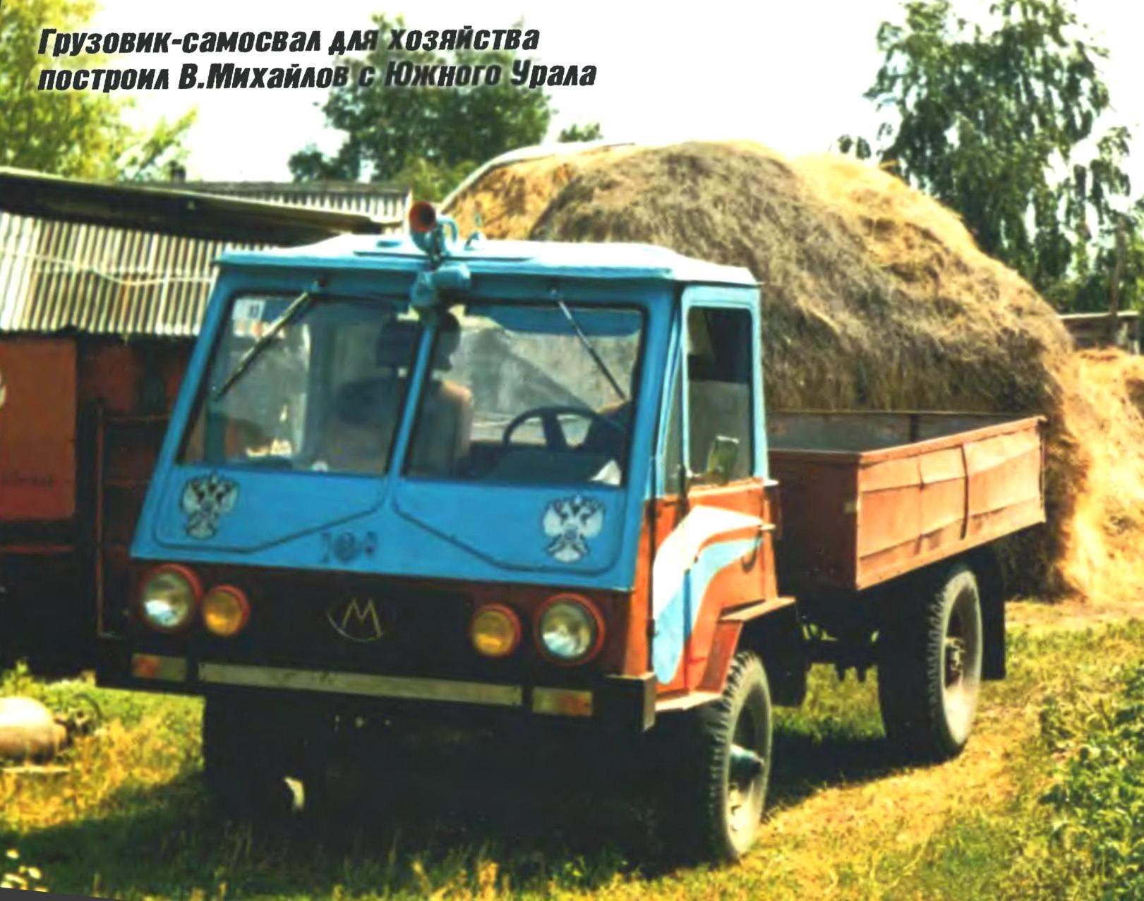
 Machine, about which speech will go, was created as a commercial vehicle, which helps to survive in our difficult time. The car gave me and my son for almost a year. I would like to thank the inspector Gostekhnadzor R. L. Markin. He is also an avid homebrew and a lot of things made with their own hands. And helped us in word and deed.
The truck I believe some invention — it is a good design of the finished units with their partial alteration of connections and collaboration. However, something had come up and do yourself — for example, the mechanism control box changes gear (transmission) located outside the engine, which, in turn, is located in the cab.
The truck is assembled from units of different vehicles and agricultural equipment, decommissioned and have not produced, so to speak, of the “vestiges”. All units were pre-renovated, most of them, in fact, restored.
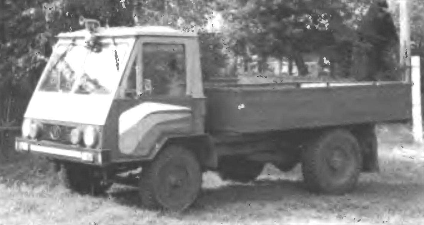
In the end, it turned out although a bit rough in execution (because it was made not on the line, and in the barn), but quite modern in appearance (or, as they say, “design”) the truck.
Frame from old mobile pumping stations of the irrigation system — it is very well suited for the size. Her spars and cross — channel 100x46x4,5 mm., However, regret not used the frame from the GAZ-53 — special alterations, it would not demanded, but it has a softer suspension and leaf springs to the same are attached via rubber mounts.
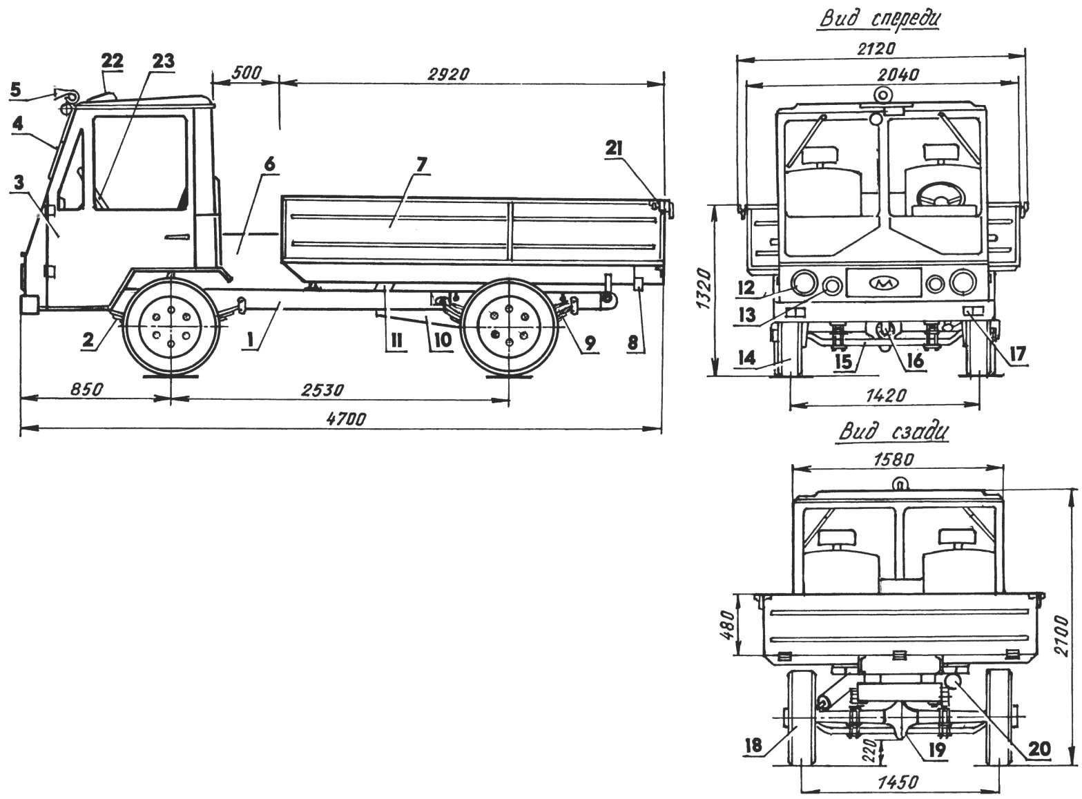
Fig. 1. Truck-dump truck:
1 — frame (from mobile reclamation pumping stations); 2 — spring (front from GAZ-51, 4 pieces); 3 — cab (tractor T-150, modified); 4 — cleaning mechanism of the glasses (GAZ-51); 5 — signal-horn (GAZ-20 “Victory”); 6 — power unit (diesel engine D-21 A1 from the self-propelled chassis T-16); 7 — body (handmade); 8 — rear lights (from the VAZ-2101, 2); 9 — podrecznik (3rd leaf from the rear springs GAZ-51, 2 comp.); 10 — muffler; 11 — body hoist (GAZ-SAZ-53B); 12 — spotlight (GAZ-51, 2); 13 — fog light (2 PCs); 14 — front wheel (from the UAZ-469, 2); 15 — front axle (GAZ-51); 16— cardan (GAZ-51, cropped); 17 — front signal light (from the VAZ-2101, 2 PCs): 18 rear wheel (tractor truck, 2); 19 — rear axle (GAZ-51); 20 — a reversing lamp; 21 — side lock body (UAZ-452, 2); 22 Luc; 23 — steering wheel (from GAZ-24)
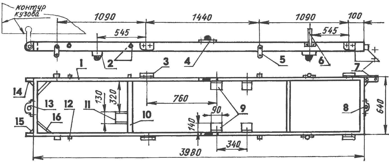
Fig. 2. Frame (modified from mobile pumping station):
1 — longeron (channel 100x46x4,5, 2); 2 — stroke limiter of the axle beam (4 PCs); 3 — retainer springs (4 PCs); 4 — emphasis pillow for the body frame (2); 5 — earring leaf springs (4 PCs); 6 — suspension strut (2); 7 — an arm of fastening of a reducer of the steering mechanism; 8 — tow bracket; 9 — mounting brackets of the engine; 10 — crossbar (4 PCs.); 11 — focus telescopic lift of the body; 12 — limit switch podreczniku (4 PCs); 13 — the drag hook; 14 — an arm of fastening of hinges of the body (2); 15 — Klondike solitaire (steel, sheet s5, 3 pieces); 16 — strut (channel No. 6, 2 PCs)
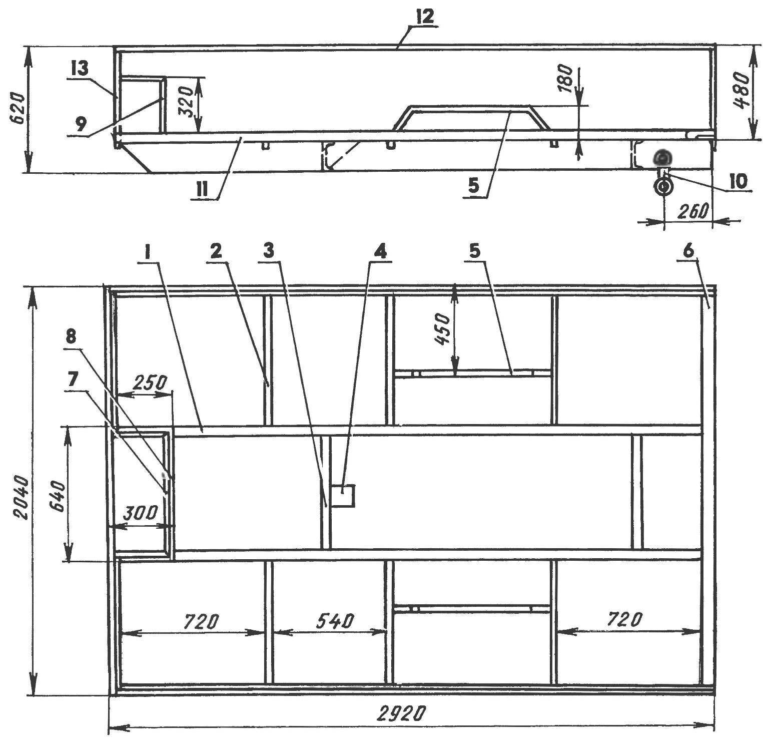
Fig. 3. Body shell:
1 — longeron (channel No. 14a, 2); 2 — edge (square tube 30×30, 6 PCs); 3 — crossbar (channel No. 14a, 2); 4 — retainer stop lift; 5 —arc wheel arches (area 50×50, 2); 6 — rear cross member (area 80×80); 7 — the top frame of the engine Bay area (30×30 area); 8 — lower frame motor niche (area 50×50); 9 — front engine Bay area (the area 30×30, 4 PCs.); 10 — a bracket of the hinge body (push rod from the engine GAZ-51, 2); 11 — lateral edge side (area 50×50, 2); 12 — amp edge bead (corner 30×30, 3 pieces); 13 — (area 30×30, 4 PCs.)
The frame can be welded and most of the same channel or a bigger room. It is important to determine its main dimensions. Frame width (my truck 640 mm) is dictated by the angles of rotation of the front wheels and their diameter, the respective sizes of the power unit and the width of the bridges. The distance between the last (base) identifies the length of the frame (I have a base 2430 mm). In turn, the base depends on the layout of the power unit and transmission.
To the frame is welded or bolted to different brackets, drilled holes for mounting all the necessary components and assemblies.
On the left side rail front frame mounted bracket for mounting a reducer of the steering mechanism. Back to the ends of both spars are welded to the brackets with the holes for the hinge mounting of the body; joints reinforced with gussets.
To the rear crossmember of the frame is welded the drag hook and the front towing bracket. On one of the intermediate crossbars mounted resistant platform, telescopic lift of the body. To the side members privernuty bolts M10 mounting brackets and earrings of fastening of springs, and between them (from the bottom to the shelves of channels) — steel cups rubber stops their progress. For the front suspension on each side member pinned strut, while the rear — travel stops of podreczniku. Two glass adjustable rubber stops on top of the body is welded to the shelves of the channels of the side members in the middle of the frame. Between the intermediate cross members to the longerons are attached four brackets (two each side) for mounting the motor.
Cab triple, attached to the frame at four points through rubber cushions. It is based on the cabin of the tractor T-150. Frame, roof, doors cropped — tailored to the required dimensions (focused on his Constitution) and thus lightweight. Old floor cut and welded a new bottom plate made of galvanized 1,3 mm steel sheet from the “key” of the walkers have long written off the combine. The bottom of the step, the rear portion serves as a support for the seats.
The glass in the door is descending. The vents do not turn, but saved, and there is a hatch on the cab roof. The windshield of the compound, equipped with two “wipers”. In cold weather the inside is blown with warm air from the heating system of the cabin. Washer not (yet do without it as to go mostly on back roads, alone, for the most part in dry weather).
The dashboard is self-made from 1.5 mm sheet steel covered in leatherette. With her left side is the instrument panel from the “Moskvich-2141” on the right — the glove box (glove box), in the mid — audio (but the latter, of course, set not necessarily). The flap in the case of the substitute: no matter when sinking a single instrument, to get to the flap you have everything. It is advisable to do both in the truck, where each device itself.
Seat first was a homemade welded corners frames covered with cloth on the foam. But then I got served from his car “Ford”. They were mounted at the edges and in the middle of the left homemade. Under it placed the tool kit.
Inside the cabin made a soft headliner, doors, walls.
All foot controls and suspension, the car VAZ-2101, from him and the shift lever. The hand brake lever from a car ZAZ — 968 (Zaporozhets). The steering wheel, the ignition and the whole column from a decommissioned taxi GAZ-24. But horn — a real rarity from the car GAZ-20 “Victory”. I even installed it on the roof of the cab. However, such a device is not the only one, there are other units of his contemporaries, unknown how preserved. For example, the front and rear axles. It is from the truck-“longevity” GAZ-51, which was very popular and good for its time machine. Although produce ceased about 30 years ago, but in the production it was the same, so did a lot of them.
With the rear axle removed regular brake drums and wheels, and instead delivered the same product with a tractor trailer 4ПТС. Got wheels smaller shestnadcatiletnie and the tread of the tyres — the Christmas tree. Let the speed be lower, but more thrust and better maneuverability. Instead of twin wheels on rear axle, left one by one. In their discs drilled new holes at the location of the six pins on the “gazonovskom” axle flange. But then did the wheel combo: drive picked up from GAZ, but it welded rim from truck wheel.
Front axle replaced the steering knuckles with hubs on similar parts from the rear axle of combine harvester SK-5 “Niva” (from harvester SK-6 “Yenisei”). After such modifications here set pyatnadtsatipostovaya wheels from UAZ. They also combined: the rims they wasowski and CD — combine. The GAZ-51 front track passed between two rear wheels, now the track is almost coincided that has a positive effect on patency. Steering — car UAZ-452. Only to reduce the turning radius, fry a little stretched out in the forge, and longitudinal thrust shortened.
The body is completely homemade. The basis of his frame are two longitudinal members and two cross-members between them from channel number 14a (140x62x4,9 mm). The distance between the side members of the bodyshell is the same as between the frame rails. Back to the ends of the spars welded on the console from the traverse area 80×80 mm on the entire width of the body.
The sides and bottom of the body is made of the same galvanized steel sheet, and the cabin floor (from straw walkers of the combine), with a thickness of only 1.3 mm, so they had to increase. Welded to the bottom rib and to the side — stand of square tube 30×30 mm. In the bottom of the body three niches: one in front above the power unit, and two on the sides above the rear wheels. Niches, of course, the “eat” part of the useful volume of the body and the wheel more difficult the discharge of bulk materials. But such a body structure reduces the loading height, which in most cases is more important.
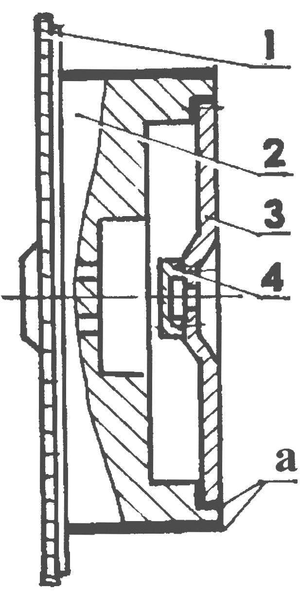
Fig. 4. The scheme of connections of the flywheel D-21А1 with the flywheel from the GAS-52 (a — modified surface):
1 — a flywheel ring D-21А1; 2 — flywheel housing D-21А1 (modified); 3 — flywheel housing GAS-52 (modified); 4 — the bearing 180203 (made according to the dimensions of the flange of the crankshaft of the engine GAZ-52)
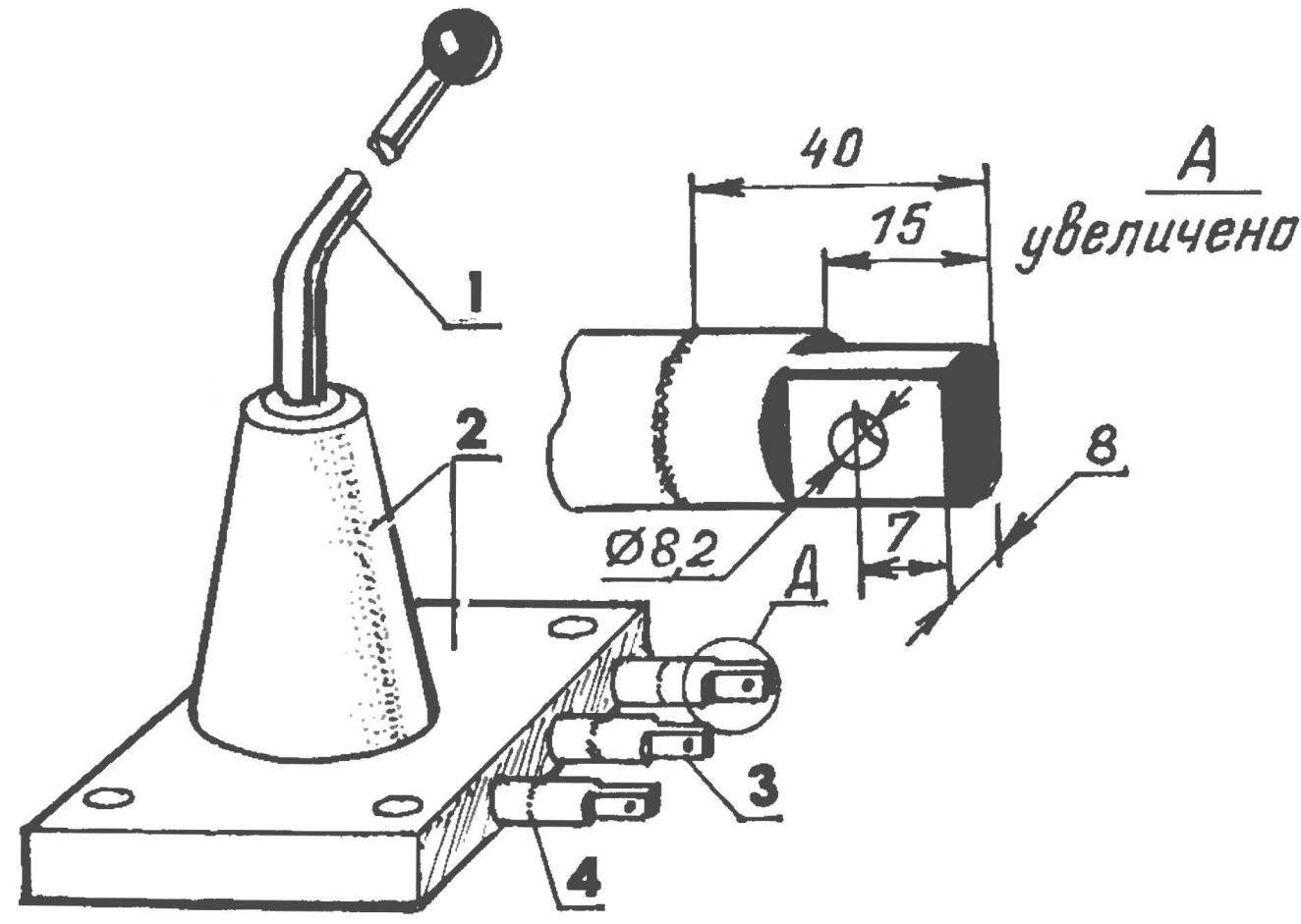
Fig. 5. Cover transmission from GAZ-51 with elongated rods (floaters) gear shift:
1 — swing arm; 2 — cover with tidal cone; 3 — elongated slides with flats and holes for connecting rods; 4 — weld
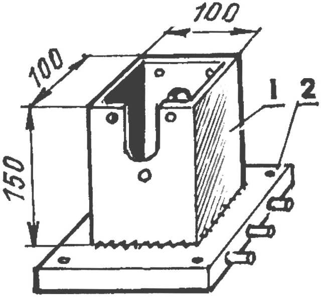
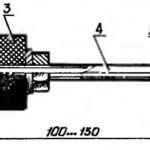
Fig. 6. Cover the checkpoint with a Cup instead of a cone for fastening gear:
1 — Cup (square tube 100×100, L150); 2 — transmission cover
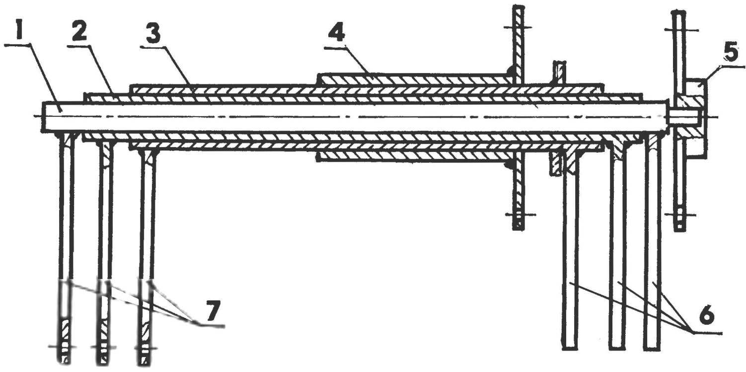
Fig. 7. New gear:
1 — Central shaft-pin; 2 — medium shaft-hub; 3 — outer shaft-hub; 4 — tube with flange; 5 — flange; 6 — the internal levers (3 pieces); 7 — outer arms (3 PCs.)
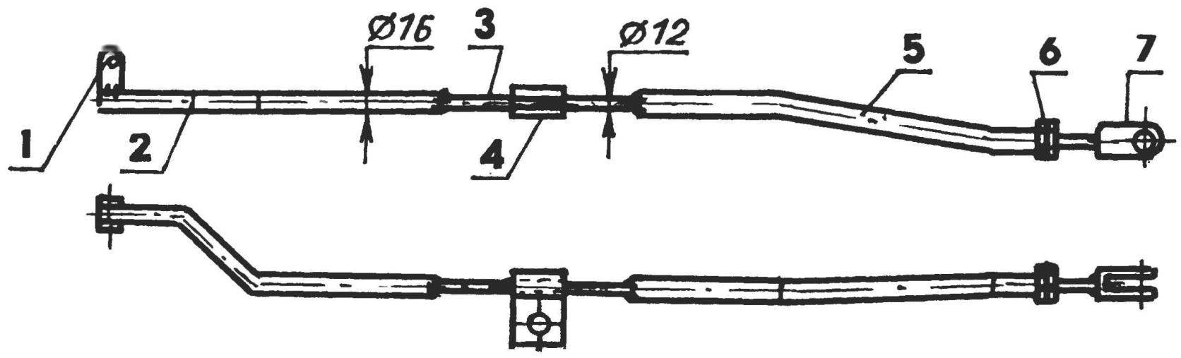
Fig. 8. Pull:
1 — eyelet for connection to the slider of the shift lever; 2 — the front part of the rod (tube Ø16); 3 — insert (round 2); 4 — clamp-bracket; 5 — the back part of the rod (tube Ø16); 6 — nut and lock-nut M10; 7 — fork-tip for connecting to the outer gear shift lever gear shift
All edges and edges of the boards and niches are reinforced with steel profiles: the bottom joint of the sides with the bottom corner 50×50 (old beds), at the top, and niches — smaller area: 30×30 mm and other sizes
A tipper. To the first (front) crossmember bolts M10 emphasis of the hydraulic lift and to the side members at the rear of the welded brackets hinges (the upper head of the connecting rod from engine GAS, 5) and U-shaped brackets under the rubber mud flaps and rear signal lights from the VAZ-2101. Tailgate body dropped down. Locks — from the GAZ-51.
And now about the main — power unit and transmission.
Engine D-21А1 —diesel, two-cylinder, four-stroke, air-cooled power of 25 HP (18,4 kW) with a maximum engine speed of 1800 rpm. Such motors are on the tractor T-25 Vladimir plant and self-propelled chassis T-16 of the Kharkov plant. The regular starter was not able to start the engine in cold weather, so it was replaced on the starter from the tractor T-40. ‘ve also got a homemade cleaner with a dry cardboard filter element from the combine.
The motor is located behind the cab. For this purpose, the distance between it and the body had to observe quite significant — 500 mm. in addition, in the middle of the front end made a little niche, but easy access is provided to all components of the engine and transmission for servicing and repair. If necessary, you can still raise.
The engine linked to the gearbox from the car GAZ-51 through the clutch basket from GAZ-53 (clutch — GAS-52). When this was not possible to avoid rework some parts and assemblies of units to their reciprocal connections.
From engine disconnect the flange and flywheel housing on a lathe bored through it a seat for the clutch basket. The end ribs at the flange of the crankcase and the casing of the clutch was removed.
The engine flywheel also had to be modified, and quite significantly. “Salt” this alteration is that I put two of the flywheel in one. For this purpose the outer diameter of the flywheel of the engine (from the rear end to the crown) bored through to such a size that it freely entered into the clutch basket (remember: she is from the GAZ-53). Further, the flywheel bored through from the inside to the other flywheel (without crown and turned outside), taken together with the clutch from GAZ-52. Pre-installed a bearing 180203 in the housing, which is machined in the form of a flange of a cranked shaft of the car GAZ-52. Both flywheel affixed with three bolts M10, making appropriate pre-threaded holes.
Connected to the combined flywheel and clutch, put them on the axle with a diameter of 17 mm and held static balance (two years of operation nothing bad is revealed). After this transmission prestimulus to grip without alterations: the front end of the primary shaft just reach the bearing in the flywheel.
Certain difficulties arose in the design and manufacture of gear. After the checkpoint (it is from GAZ-51) is far away from the lever behind the cab and behind the engine. But, in the end, decided this issue.
The principle of operation of the mechanism borrowed from the self-propelled harvester, but some components and parts had to fit under existing units. First, another old transmission from GAZ-51 took off the cap complete with lever. It was removed from the interlocks of the two speeds and shift forks. Switching rods (now they only perform the role of slides) on one side lengthened by 40 mm, privaris to them butt of the same diameter steel bars. Welding was performed according to the “dubbing”, soshlifovat seams to the surface of the rods so they do not interfere with the slide blocks to move in the sockets of the cover. At the ends of extension cords were made by flats between which the drilled hole with a diameter of 8.2 mm. Bottom cover closed the bottom of a steel plate and set it on the floor of the cab.
Cover gearbox also underwent alteration. It cut off the cone and remove it with the lever. In its place welded a Cup — cut square pipe 100×100 mm with a height of 150 mm. Side at the top of the tube is made a groove for the installation of a self-made gear.
The switching mechanism was not only original, but, in General, not too big and even compact. It consists of a Central round core and several pipes of various diameters and lengths, inserted into one another. The condition in the design are respected only one thing: the tube-in-tube and on the web sat free, with a small gap (and therefore the size of the parts of the mechanism in the drawing is not cite, and give only the scheme of his device). To the rod with one end attached to the flange, and the outer pipe wearing another pipe welded to it in the same flange. The ends of each tube of smaller diameter (and stem) are on both sides of her put on larger diameter pipe. To the protruding ends (both sides) welded to a pair of levers, the free ends of which are truncated by one line.
Three in the arm (one side) placed in a glass and their ends inserted in sockets in the slide and fixed there with screws. Top glass the lid is made of sheet steel (using rubber gasket). The tube mechanism is lubricated by splash of oil from the transmission. The other side of the mechanism secured to the transmission case. Leverage the same through drilled at their ends holes, connected with the ends of the rods.
The configuration of each thrust its own, and is quite convoluted, because the twisting thrust. Therefore, cite only the figure, revealing a design of traction.
Since thrust is quite long, the gear change was not very clear. Had traction to cut and weld it in them, the intermediate rods are thinner, which concluded in a tie bushing, and the latter is mounted on the fixing pin of the engine, thus obtaining, for each additional intermediate thrust bearing.
Two pull switches for two speed, one of the first and second, second — third and fourth, and third pull —back. So the shift pattern remained normal, the course of the rods had to make a crossover. Adjusting the length of the rods, provided a clear shifting.
The gearbox is mounted a small gear box. With minor alterations to the mating surfaces to the last attached hydraulic pump NSH-10. It is used only for lifting the body, and its capacity is enough. The pump includes a lever together with transfer box.
Telescopic — car-truck GAS-SAZ-53B. The lower end of the lift connected with emphasis, located on the crossbar of the truck, the upper end — with a focus on the crossmember of the frame body. Oil tank — the receiver of the tractor truck located on the right side of the car under the body.
The fuel tank was first tank 60 l. But where from to get the money to fill it completely? And empty it was heavily rusted, clogging the system. Now stands at 27 litres (per day more than 10 liters do not spend).
And the last painting. I painted the car with oil paint, brush. Of course, if funds are available the finishing can be done better. But I pass inspection without comment.
The mass of the truck — 1800 kg, load capacity up to 2 tons It can pull a trailer weighing up to 3 T. However, the engine in this case should have been easy, but so hard to load the machine it happens rarely.
“Running” truck can up to 60 km/h and the lane is not far behind from the factory truck, but the maximum allowed speed is 50, and the trailer is 40 km/h.
V. MIKHAILOV, S. Novopokrovka, Chelyabinsk region
Recommend to read
 EXPRESS”STOPPER”
Quickly and securely "to drown out" the water pipe or radiator hose when testing it for leaks by using a simple device. By rotating the handle the rubber grommet sandwiched between two...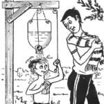 THOUGH RUKOMOINIKOV, THOUGH — SHOWER
Indeed, the proposed "wash" the device for use in the country may be universal — it will depend on used plastic containers: a two-liter bottle enough to wash hands or dishes, and...
