FLIGHT ELECTROLET

AEROBATIC ELECTROLET

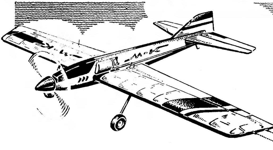
Judging by the letters from our readers, the interest in the model aircraft with electric motor is not reduced. Comes a lot of questions about the challenges of producing interesting flying machines and development of specific projects. One of them we want to acquaint the followers of electroperu. Very effective control line aerobatic model created by A. SUHANOVYM from the city of Astrakhan. In addition, they built “nilotica” interesting minimal use balsa, which gives the possibility of playing in almost any conditions. If necessary, balsa items without much damage to the mass of the model can be replaced made of lightweight Linden (in this case, TopMenu blanks should be reduced in half to two times).
Aerodynamic design cord “pilotage” calculated under the terms of the limited capacity of the plant is the wing is very high for these cars elongation. Developed by relative square control surfaces and increased shoulder stabilizer that also has high elongation are improving the maneuvering characteristics of the model.
 
Before beginning work on construction of the model need to execute drawings of the main elements in full size on thick paper. Diagram of the frame of the wing will be simultaneously and Assembly Plaza, so the sheet of drawings bearing planes must be attached to the flat Board to the slipway and close top with clear plastic or Mylar film.
 
The fuselage can be made in two ways: one-piece, which gently saw through the window a jigsaw relief, or presents stacked frame made of Linden or pine slats. The second method is more time consuming, but it will give a lighter and more durable option. In any case, after the completion of works on the fuselage of its side faces are roughened, then the selected window (IPI gaps between the slats of the frame) are filled with foam, pre-cut into plate-blanks of appropriate thickness. After a second Stripping the panel of the fuselage glued tissue paper (glue, not solvent material of the foam). And then in the panel cut window under the motor, wing and stabilizer.
The next stage of manufacture is the preparation of materials and workpieces for wing elements. As already mentioned, balsa for the ribs may be replaced by a thin fake plates. A set of ribs can be cut serially, using as template a specially made precise in the form of a plywood rib. If the knife is for you difficulty, it is better to collect on the two threaded studs in the package the required number of pieces and process them together along two edges attached with package plywood templates.
 
For rails of the frame of the wing are selected high-quality grained pine. Reiki gauge on the device, known among modelers called “broach”, by plane. The Assembly of the frame is directly on the stocks, which details the kiss light weights. The best binder — empit or other reliable vitrocla. In the ready set mount bellcrank control of electrically insulating material attached to it electrical wires to simultaneously perform the functions of management model. To the same point of the swing by soldering the stripped areas of the wires and attach the flexible wire to power the electric motor. Last better to do with a stock length so that when the debug control on the finished model didn’t have to develop them.
 
In the outer end of the wing (i.e. the right “console”) stick with a weight 15 To the rails of the spar thread with glue secure them curved wire OVS diameter 1 mm landing gear, the ends of which put small wheels from broken toy cars.
 
Fig. 1. The main geometric parameters of the model
 
Fig. 1. The main geometric parameters of the model.


R and p. 2. Wing:
 
R and S. 2. Wing:
1 — control cables (patch cord ML), 2 — tube output cables (polyethylene), 3 — plate fins (balsa with thickness of 12 mm or foam PVC), 4 front flange (pine rail with 2 cross-section 3 mm), 5 — rib (balsa 2 mm thick), 6 — spar Assembly, 7 — trailing edge (pine rail cross-section 2 10 mm), 8 — strengthening of the spar for mounting the rockers, 9 — rocker control (Micarta or textolite with a thickness of 1 mm), 10 — pad for output thrust ailerons (balsa 2 mm thick), 11 — Central wing (drawing paper or thin cardboard on both sides of the wing), 12 — bracket flaps (wire OVS 0 1 mm “tubular liner lugs), 13 — tail boss (Linden), 14 — shank (balsa 2 mm thick).


Fig. 3. The fuselage
 
Fig. 3. Fuselage:
1 — force frame’ (Linden thickness ZMM of the framework or skeleton of the fake strips cross-section 2 mm 3), 2 filler (light foam thickness of 3 mm), 3 — the outline of the window under the motor, 4 — the outline of the window under the wing, 5 — an outline of the window under the stabilizer, 6 — Kiel (thin dense cardboard).


R and p. 4. Wing section
 
R and S. 4. Wing section:
1 – front edge (pine rail cross-section 2 X 3 mm), 2 — rib (balsa 2 mm thick), 3 — beam flange (pine rail cross section W X 3 mm), 4 — rear flange (pine rail cross-section 2 10 mm), 5 — Aileron (hollow profile of paper or thin cardboard).


Fig. 5. Stabilizer with elevators
 
Fig. 5. Stabilizer with elevators:
1 — power trim (paper or thin cardboard), 2 — power trim wheel (drawing paper or thin cardboard), 3 — liner (lip), 4 — connecting bracket rudder (wire OVS 0 1 mm), 5 — root rib helm (lime), 6 — spar (pine rail section 2X3 mm), 7 — the installation location of the hinge suspension steering, 8 — terminal insert (balsa).


Fig. 6. The linkage of the ailerons on the wing
 
Fig. 6. The linkage of the ailerons on the wing:
1 — wire loop-sernr (OVS wire diameter is 0.5 mm; the ends before gluing to clean up and wrap a thin thread), 2 — rib, 3 — rear edge of the wing, 4 — Aileron (hollow profile). The linkage of the elevators is similar.


Fig. 7. Fabrication of ailerons and rudders:
1 — root rib-liner (lip thickness: 2 mm), 2 — power metal (paper or thin cardboard), 3 — end liner (lime 2 mm thick).


The frame is sanded with fine emery paper, and the center section is covered on top and bottom wetmanski paper. The cording has the same total wing — Mylar film or micuenta long-fibre paper. The first is attached to a divorcee about half (solvent No. 647) the glue “Moment”, “Unique” or “Contactor”. Micuenta paper — amalite, and varnish the entire surface is covered three or four times to stretch and Shine. It is very important postaratsya to avoid at this stage, the appearance of twist in the wing, which are then corrected it will be very difficult.
Stabilizer and all control surfaces are made by a single, very simple and effective technology. It is used as “power” trim thick paper or thin glossy cardboard. Such technology allows to save a lot of time, while being robust and lightweight design of the rudders. When mounting them on the stabilizer and wing should maximise ease of running and debug deviations so that during the course of the elevators to + 40° ailerons would be deviated in the opposite direction by ± 25°.
Rod linking the control horns of the ailerons (although more accurate to call it on aerobatic models, these control surfaces flaps) and elevators from the wire OVS 0 0,8 mm.
 
For aerobatic models, an electric motor from the common RC toys-car “Bend”. Of course, other variants up to high-powered motors with magnets made of rare earth metals. The engine is mounted almost in the center of gravity of the model, and spinner of the propeller it connects the extension shaft is supported in the nose of the fuselage on a bearing of bronze. The shaft can be hidden inside even as thin as the proposed model of the fuselage. However, from an operational point of view, better to spend it with the right side outside. The propeller wood is chosen according to the diameter and step by practice depending on the characteristics of the motor and power supply.

Recommend to read

  • WITH THE AMMONIA — TO THE BATTERYWITH THE AMMONIA — TO THE BATTERY
    This advice will be useful to motorists, loving care and not shy to Tinker themselves with their car.     If you want to remove razrushivshij the electrolyte from the surface...
  • LOADER – THE CAR ITSELFLOADER – THE CAR ITSELF
    Original car loader, which is designed by the young technician Alexander kobzevym at Voronezh oblsud, we offer the readers. At the VII regional scientific-technical conference of...