The layout of the workbench such that it can be divided into three parts: the base nodes of a clip and two desktops. But these parts are conditional — they are the workbench is divided for transportation, and, for example, for compact storage it can be dismantled into smaller units and even details.
The base consists of four legs made of square pipe 40x40x2 mm. cross-section of the Upper ends of the legs are rounded, and the holes are closed with plugs welded to the pipe wall is not flattened when tightening to the body node of the clamp. The lower ends of the legs left nezaklyuchennym that the bench did not slide on a hard floor. If you want to install the workbench on the ground, to the lower end should be welded glides — steel plate.
In the upper part of the leg dock in pairs to the nodes of the clamp, and the height fixed crossbars, part provocame and spacers made of 2 mm steel strips, bent in the corners of 20×20 mm.
The height of the legs can make another and fit them to your height. The node of the clamp (there are two) consists of a body (segment of a rectangular tube section 50x30x2 mm) screw (M12 stud construction) with uterine nut and handwheel with handle.
Lead screw placed in the body with screwed on him nut and uterine installed it on two supports. Support made of softer steel and therefore are used for all screw and slide bearings lubricated with grease constitently.
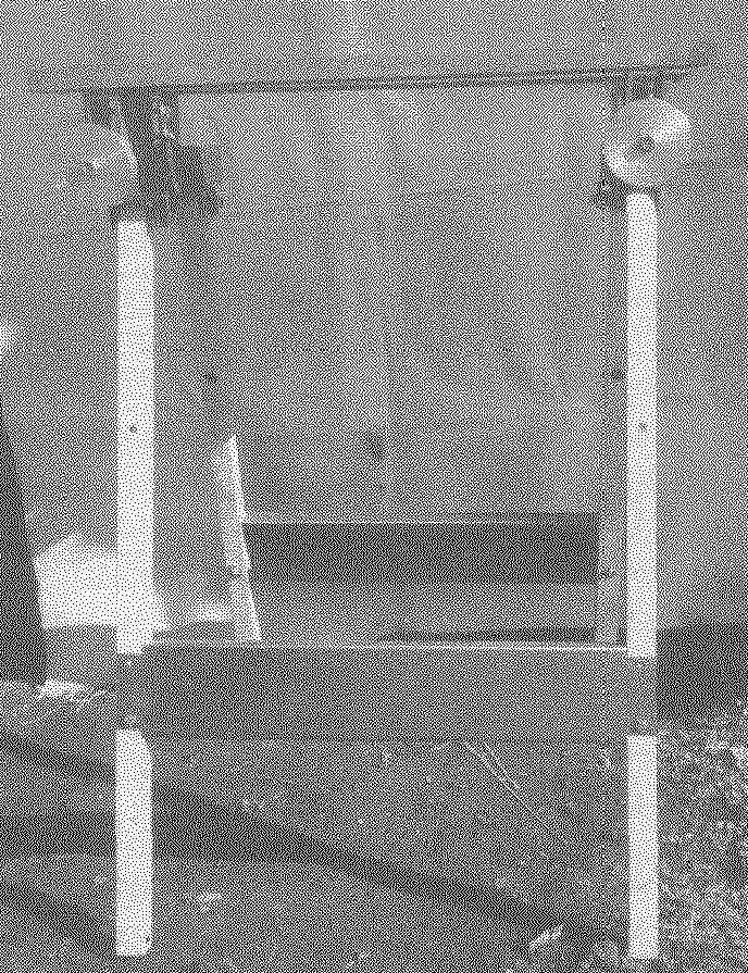
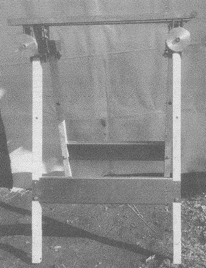
Fig. 1. Folding bench:
1 —boss (duralumin D16T, square 40×40, 4 PCs.);
Fig. 2. Node thumb:
1 —handle (steel, round 20): 2—flywheel (D16T, circle 90); 3—mount the handwheel on the lead screw (M8 nut); 4—distance sleeve (steel 10, round 20) a; 5—pole screw (steel 10, the sheet s10,2); 6—screw (building stud M12); 7—housing (rectangular tube 50x30x2); 8—bracket legs (steel, sheet s2, 2); 9—uterine nut (steel 35, round 32); 10—base table (a steel rectangular tube 50x30x2, 2); the second part is mirrored; 11 —bracket table (steel 10,2). the second part is mirrored; 12—clamp bracket (M4 bolt, washer and nut, 4 set).; 13—bearing retainer screw (M3 screw, 2 pieces); 14—mount the base of the table to the fallopian nut (M4 screw, 3 pieces)
One support (from flywheel end) is welded to the shell, and the other is secured by two M3 screws with countersunk heads.
To the bottom of the casing are welded two brackets for connection with its pair of legs. From the top, on one end of the body (from flywheel side) welded base for mounting one of the tables (there are also two). The base is made of rectangular tube 50x30x2 mm. Other reason (the second table) is screwed to the fallopian nut with three screws M4.
To the grounds through the bracket attached tables, with one table to a pair of stationary bases, and the other to a pair of movable (installed with screws M4 nuts on the fallopian). To the brackets, the tables are bolted to MB with countersunk heads.
At the maximum displacement of the movable table to a stationary both of them form a single, fairly large plane.
Braces, along with tables have the ability to be installed on the grounds at fixed angles: 30, 60 and 90 degrees.
The plates of both tables nasverlennye the number of ordered holes (five pairs along). In the holes you can insert the lugs, attaching them from below with screws with wide washers to the table. Pushing (pushing) the sliding table to fixed and changing the position of the lugs can be mounted on a workbench by the method of clutching or release of the parts and products of different sizes and complex configurations such as for bonding and processing.
Recommend to read SUPPORT WPOTY As a rule, furniture shelves mounted on pins inserted into holes of the side walls. These nodes can be improved: choose in the shelf a groove into which and hidden support. In addition,... HELP CROCODILE If the crocodile clip soldered to the curved steel rod with a handle from a file, you will get rid of the inconveniences associated with driving in small nails.
 To design present a universal (I believe) bench is a necessary desktop DIY I came across several years of studying technical creativity. It was designed based on their needs. But I think about the same requirements to such equipment his Studio have most other home handymen. Workbench foldable and small in size. However, due to the original pressure of the knot on it to handle you can pin a fairly large parts and products, installing them in a vertical plane, and at multiple fixed angles.