The seat bracket is welded from steel angles 40X40 mm. its Dimensions are selected by growth driver. The Seating position on the bracket can be adjusted in the longitudinal direction. Frame steps bent from inch water pipes. Together with steel foot pads it is welded to the center sill of the front and serves as a support for feet of the driver, a bracket for the brake pedal and safety arcs.
The bracket in the lower part of the housing of the rotary speakers designed for mounting there of the lifting device For the attachment of the tool shown on the front: bulldozer knife, fork. This task copes the lever of a manual brake from the car GAZ-51; it allows the spring latch to lock the lever and connected with it the tool in the raised position
Fig. 5. The front frame :
1— fork swivel wheels 2 — spinal beam pipe 45X30 x2.5 mm, Z — bracket lift lever 4 — steering column 5 — swivel shaft, 6 — wheel, 7 — brace, steel plate of 8 mm thickness, 8— seat bracket, angle 40X40 mm, 9 — seat 10 — arc running boards,11 — base area.
The engine cover is an integral part of wings wheels from steel sheet of thickness 0.5 mm.
To increase the adhesion with the soil while ploughing, deep cultivation and improvement of patency, the wheels are covered lugs. Rim get, turning into a ring of steel strip with a width of 100 mm and connecting the junction of the two bolts. Outside there is it welded or riveted corners 8 X 25 X25 mm. Four of them have a length of 160 mm. Tilting the speakers for the width of the rim part, get the side supports fixing on the grouser wheel.
Control knob for motoblock two-wheeled variant of the welded steel tubes with external ø 22 mm. In this case, they are easy to put on motorcycle clutch lever and turning the handle “gas”. The crossbar is made of pipes of smaller cross section.
The tools made from materials available: steel angles, tubes, rods, sheet metal and assembled using elements of the decommissioned equipment: ploughshare from the plough, the cultivator arms.
For ploughing of small areas walk-behind tractor is equipped with odnodolnym plow stands out of durable lumber with shingles.
A cultivator with a working width of about 800 mm has three removable legs. Having made several sets with different width of the working edge, they are easy to replace — depending on the treated crop.
Frame transport trolley, designed for a payload up to 400 kg metal, welded squares of 50X50 mm. On a common axis mounted two wheels from the map. Body type — wooden, with folding rear Board.
Dozer blade — steel sheets with a thickness of 3-4 mm., its Width is 700 mm, and although the thrust developed by the motor-block with cleats, quite large, it is designed mainly for snow removal.
Forks to collect grass clippings in stacks made of welded to the frame corners and steel rods ø 10 mm.
To gather grass into piles, clean the garden from dry twigs to clean the forest clearings will help tractor rake — harrow. For their load-bearing cross beam you can take a steel pipe d 40 mm, and the teeth are bent into a semicircle of thick steel wire.
R and S. 6. The PTO-driven stretcher :
1 – rod, 2 — finger, 3 — spherical bearing. 4 — the crank wheel 5 — bearing No. 60302, 6 — shaft, 7 — spacer sleeve. 8 — the case. 9 — cover with felt seal. 10 — star 11 — spacer, 12 — housing mounting bracket, pipe 45X30 x2,5 mm. 13 — the rack 14 — rocker 15 — bracket 16 — rod rolling knife. 17 — guide. 18 — movable knife of the mower.
A PTO shaft to drive the power tool is made in the form of individual removable node. His chiseled steel housing on two bearings No. 302 (60302 better— they have a protective washer) the shaft. At one end is attached to the driven sprocket and the other driving flange or wheel for the crank connecting rod mower. The housing is welded to the bracket of a section of a pipe 45X30X2,5 mm, by which the entire Assembly is put on the spinal beam frame. The place of fastening the through-bolt is specified by the length of the drive chain.
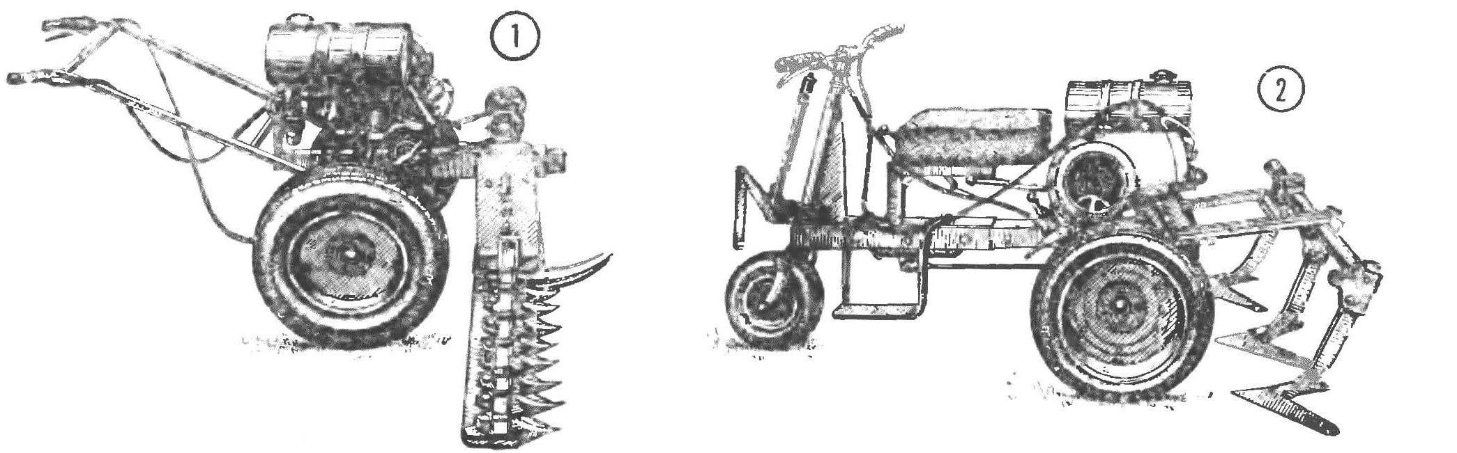
In our machine the PTO shaft is mainly used for the drive of the mower, so both mechanisms are combined in one unit. Front mower — cut channel No. 12 is connected to the bracket bolts to the PTO shaft. And its lower part is installed the working parts of the mower is stationary, and above it, in plate rails — agile. Width — 1000 mm. the Movable knife is driven by a rod from rocking, the axis of which is fixed to the strut bracket. The conversion of rotation of the PTO shaft in the reciprocating stroke is the crank gear.
Set the mower on the frame can be in any layout of the machine. On three wheels well to mow an open field, meadow, and, taking off the front and securing at the rear frame brackets of the control knob, it is convenient to work in the garden between the trees and on the forest clearing. A small support wheel under the beam will help to sustain the height of the slice.
The design of the walk-behind provides the following options for mounting a working tool. The front frame brackets are used to connect the dozer blade, and forks. Rear — when a two — wheeled layout for the control sticks, while three-Wheeler — for the cultivator, harrows, tractor rake. The truck hooking it with the finger to the center sill of the frame. And for plowing on the two-wheeled walk-behind plow is secured by a clip of the “ladder” directly to the beam, with the longer part of the working edge toward the engine. Since the rear axle has reverse, tillers can work, and moving in the opposite direction.
The levers of power plant equipment and accessories arranged in front of the vehicle near the driver’s seat. There are levers of the gear box, reverse the bridge and lifting the hinged rear of the equipment. On the right is fixed footrest brake pedal, and the wheel clutch lever and hand grip throttle of the carburetor. Start the engine by kickstarter, the lever is removed.
Recommend to read MAGICAL TRANSFORMATIONS OF PAPER His appearance in the editorial was met with a, frankly, no enthusiasm; preliminary telephone conversation were no signs, it seemed, nothing sverhinteresnogo. Homemade paper? Well,... IZHEVSK CLASSIC “THE MUSCOVITE” TO “PLOT” In the distant 1960-m to year, in accordance with the doctrine of the Association of school and life, our 10-grade "B" in full force was aimed at a large aviation plant with a mysterious... 
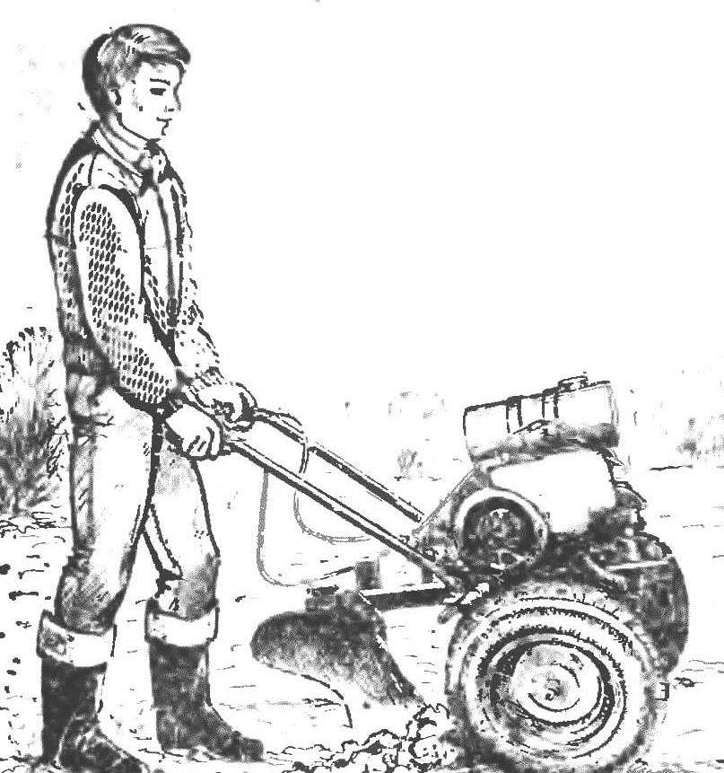 Compact versatile self-propelled machine MOSM-1 — so named his design the young wizards of the circle modeling and the design of agricultural machines Novokosinskaya high school in Dagestan. With various attachments it performs plowing, cultivation, sowing, harrowing, mowing hay and collect the dried grass in rolls and stacks; trucks in the tow truck different loads, and in winter helps to remove snow. From the PTO can be powered and other power tools — circular saw, drill, water pump. Such a wide range of works became possible due to the universal structure that combines advantages of microfracture, tillers and motorised. Details about the structure of the machine says the head of the circle K. M Kurbag.