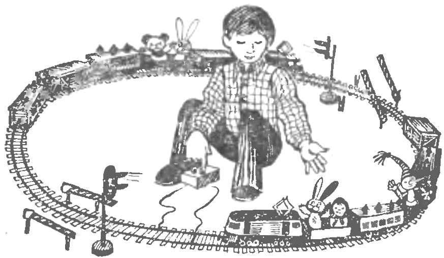
 Children’s railway — one of the most loved games boys. But if it has control elements, for example a traffic light with automatic switching of lights, the game becomes even more fun.
Diagram of traffic light (see picture) is a time switch on the transistors T1 and T2. In the collector circuit of T2 relay R1. Through a break contact R1/1, power is supplied to the rails of the railway, and with them on the locomotive. Switching contact R1/2. includes a green or red lamp of the traffic light. Thus, the model is moving on a green light.
Under the rails includes a contact that closes under the weight of the locomotive. When capacitor C1 is charged through the resistor R1. After the passage of the electric contact opens, and the negative charge of capacitor C1 opens the transistors T1 and T2. In this state they are as long as the capacitor C1 is discharged. The discharge time of C1 (15) change with the variable resistor R2. While the transistors are open, the contact R1/1 is open (electric), contacts R1/2 turns on the red lamp of the traffic light.

When the capacitor C1 is discharged, the circuit comes to initial state: relay de-energized, the light turns green, and the locomotive is in motion.
In the scheme of traffic lights is used: relay tap changer with current of 15 mA, the diode D2 or D9 (put it to circuit EMF of self-induction of the relay when you turn off transistors). Powered the circuit from one battery 3336L. As KN-1 is used the contact plate from the old relay.
The traffic light can be done according to the drawings published in “M-K” No. 4, 1975.
The installation location of the contact KN-1 under the rail are selected so that the locomotive is stopped a little before reaching the traffic lights.
If desired, the rail automation can be supplemented with automatic gate, descending with a green traffic signal. It will be powering an electromagnet or microelectronical driven релеР1.
NIKIFOROV


