 Dodging huge rocks, deep crevices, and streams of boiling lava, to distant planet moving vehicle. Lightning, crumbling rock, and he continues the study takes soil samples, atmosphere. The vehicle is not operated on the radio: he makes decisions himself.
While this is only a dream. Unknown planet, a small model. But she knows how much: goes on light, go around obstacles and water obstacles. This model was built by the guys from the mug of instrumentation Moscow Palace of pioneers (supervisor O. F. Belsky).
Schematic diagram of the lunar Rover is composed of modules: “orientation to the light,” “water hazard”, time-switch, logic, and power supply (Fig. 1).
When the light hits the photoresistor R1, its resistance drops sharply and the base of the transistor T1 there is a negative voltage. The transistor opens, its collector current increases, causing the relay R1. The contact R1/1 includes the relay R6 which, in turn, your contacts R6/1 opens the supply circuit of the motor M1 (Fig. 2). Since the diode D1 is locked, the current through it does not leak, and the relay R5 is not triggered. When light falls on photoresistor R2 turns off the motor M2 (open contact P7/1).
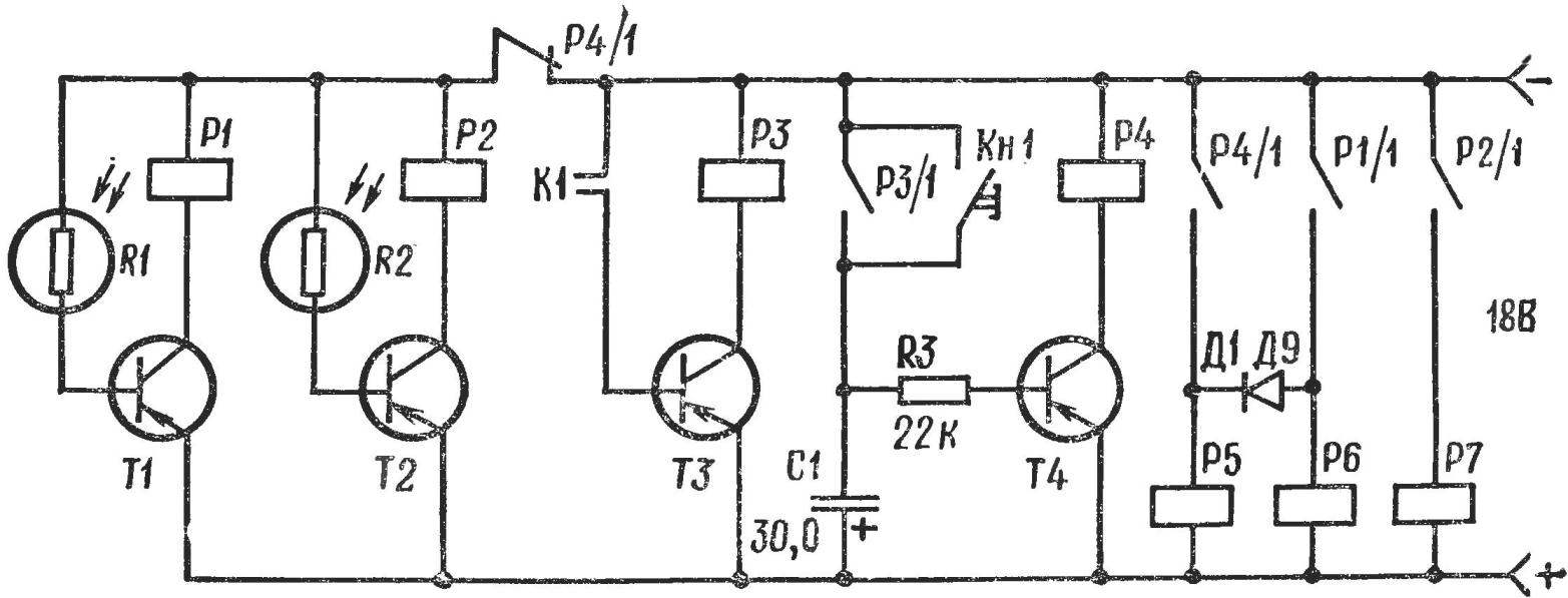
Fig. 1. The concept of “planetary”
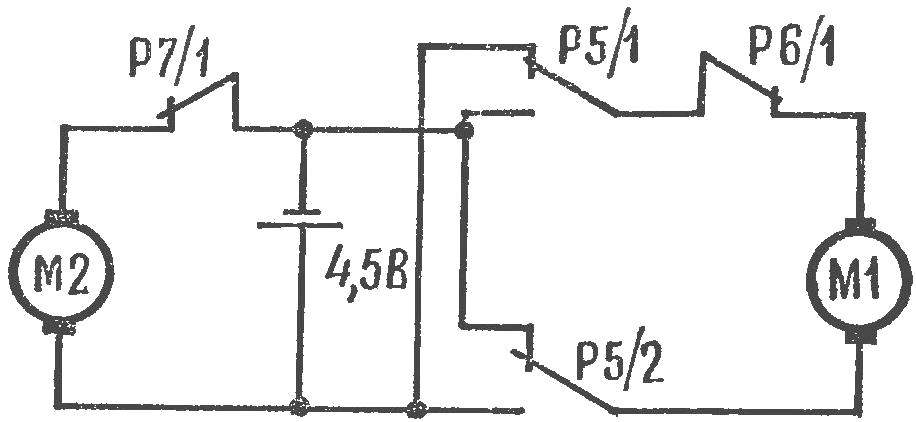
Fig. 2. Circuit switching motors.
So turn off the left, the right motor, and the planetary Rover is suitable to a light source.
When the plate of the humidity sensor C1 fall in the water, they come into contact (water contains positive and negative ions which conduct electricity). The transistor T3 opens, in its collector circuit relay R3, which contact R3/1 includes the time relay.
When contacts R3/1 or KN1 charging the capacitor C1. When the negative voltage on the base of T4 will reach the value at which the transistor opens, in the collector circuit of relay R4. The anchor remains energized until the capacitor C1 is discharged and the transistor T4 will not be closed again. When the contact R4/1 include relays R5 and R6.
Changing the direction of rotation of the motor M1 is performed by switching the polarity of the power supply through the contacts R5/1, R5/2. The lunar Rover around the obstacle and then continues the movement. Relay P4 not only commutates the motor, but unplug the unit “focus on light” contact R4/1. Suppose the model has hit a stumbling block and at the same time on photoresistor R2, the light gets in. If you do not detach the unit “orientation to the light,” the lunar Rover will stop.
Logical relay unit P4—P7 reacts to the signals coming from the sensors “light”, “water”, “obstacle” and in accordance with a set program produces command: “start”, “stop”, “turn”. Thus are coordinated the incoming signals and actions.
DESIGN
The model is made on the basis of the self-propelled chassis of the toy with two independent motors and caterpillar chassis (Fig. 3). On a chassis mounted circuit Board and an Autonomous power supply.
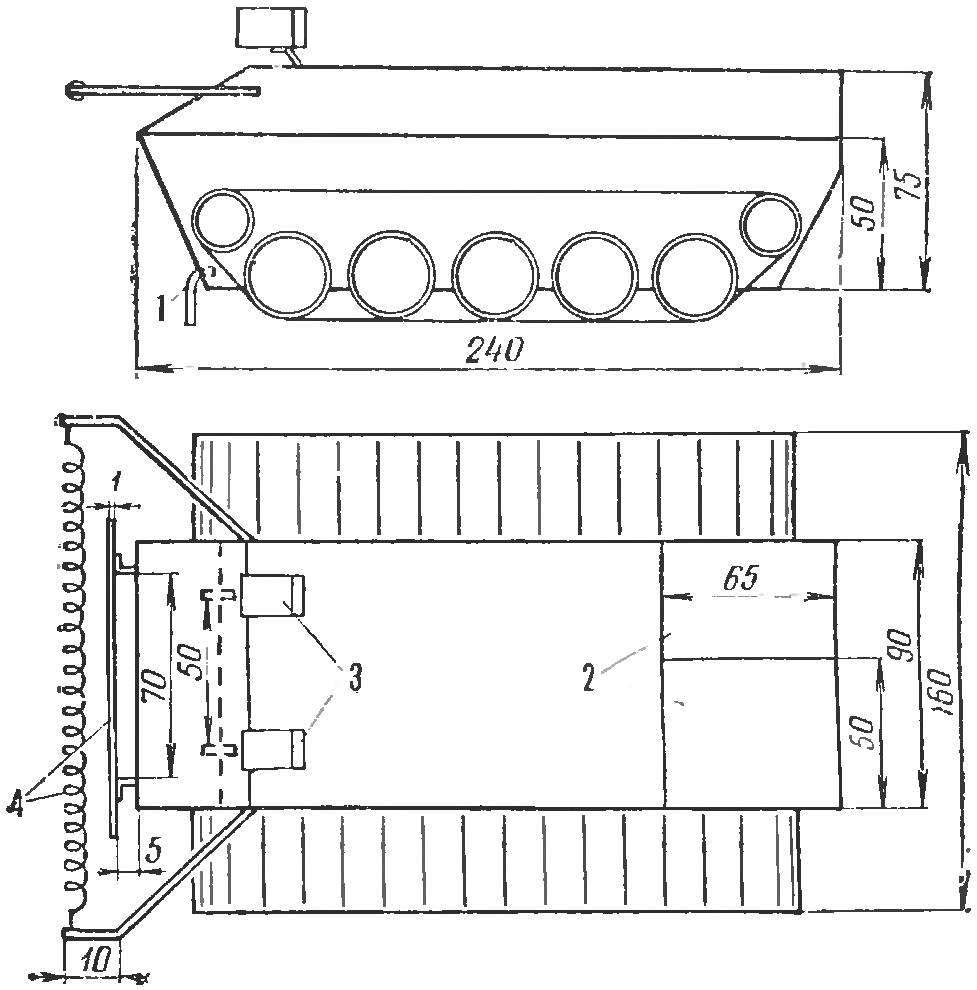
Fig. 3. Tracked platform “planetary”:
1 — sensor the “water barrier”, 2 — engine Bay 3 — photosensor, 4 — sensor “barrier”.
On the Board size 46×90 mm mounted blocks “orientation light”, “water barrier” and the time relay. On the Board size of 50X20 mm logical unit is assembled. Both boards are made of insulating material (textolite, Plexiglas, plywood) with a thickness of 1-3 mm. Installation — mounted or printed.
The sensor unit is “water barrier” made of tinned copper wires Ø 1-2 mm vertically and located in 1-2 mm from the floor.
Transducer block “obstacle” is constructed as follows. Two segments of the copper wire Ø 1-2 mm is soldered a strip of sheet metal the same length as the body, and a width of 10 mm. the Second contact terminal — floating spiral — wound turn to turn tinned copper wire Ø 0.5 mm on mandrel Ø 1-2 mm. Both the contact wire attached to the body of the model.
Under the power supply cases are made of Plexiglas. Their sizes depend on used items. To power the engine used two connected in parallel battery 3336L, and for the power electronic circuit 12 elements of PBS.
DETAILS
The details in the scheme — of any type. Resistors — MLT, ULM. Capacitor C1 is electrolytic (K50-6, K50-3) working voltage below 15 V. the Transistors T1—T4 МП25, МП26, МП39—МП42 with any alphabetic index. D1 — point diode D2, D9. Photoresistors R1, R2—FGC-1. You can replace the transistors with the head filed off. Electromagnetic relays R1—R4 рЭС10 (passport PC4.524.303.308), РЭС15 (passport PC4.591.002).
As R5 in a logical unit is used as a relay RES9 (RS4.524.202); P6, P7 — РЭС10 (RS4.524.303).
The ESTABLISHMENT
Start with the unit “orientation to light.” Photoresistors are placed in the tubes (Fig. 4) and to achieve that the light from one source does not impinge simultaneously on both photoresistor.
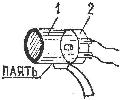
Fig. 4. Photo sensor:
1 — tube, 2 — photoresistor.
Then adjust the time relay. Selecting the values of resistor R3 and capacitor C1, to achieve that the lunar Rover is turned at a certain angle.
Sasha GOLUB, student of school № 588 of Moscow
Recommend to read
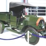 IT ALL STARTED WITH AMO
On the night of November 1, 1924, the workers took the first car entirely manufactured in the factory AMO. One of the mechanics, bent his head low in front of the radiator with the...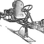 SNOW GO-KART
It's easiest to say: "When I grow up, I'll get behind the wheel of a car, take a plane into the sky, build what I dreamed of..." But it turns out that many dreams can come true even at...
