Application in construction automotive hub due to install it, double-row bearing. Another advantage of such hub – and-swivel hinge mechanism that compensates for inaccuracies of manufacture and adjustment alignment of the two hubs. Perhaps the use of hubs and half shafts from any front wheel drive car.
The hub from the “Okie” gently connected to the mixer via the damper rubber washer, also from the 16-mm conveyor belt. The use of damping rubber washers provide smooth start and operation of the mixer.
The second hub consists of a housing with two ball bearings, shaft: one end connected to another hub using a rubber washer; on the other end a belt pulley. Pulley is used from air compressor MAZ.
Due to the fact that the mixing tank “rides” on the bearings in the cradle and not connected rigidly with the hub, and not “hanging” on it, the vertical axial load on the bearing virtually no, which ensures its long service life.
Electric gear motor performance: 600 W, 380 V, 20 rpm on the output shaft.
Ball bearings in the gearbox are replaced by double row roller.
Due to the fact that the drive was supposed to be used only on a single phase AC motor stator windings and the scheme of its inclusion have changed. Windings are made of enameled wire and fiberglass wrapped additionally with a thread thickness of 0.1 mm is tightly, turn to turn. This provided a reliable high-voltage and high-temperature wire insulation, eliminating the possibility of inter-turn short circuit in the windings and the output of electric motor failure. Even with the “burning” of the enamel on the wire winding short circuit impossible. After gaskets are windings in the slots of the stator impregnation of the windings was not made, which provided the best heat transfer.
Connection diagram of the windings was changed. One of the three was connected in parallel to the other two, which provided an additional EMF and eliminated back EMF of a coil, hindering the work of the three-phase motor on a single phase and leading to a loss of power.
Such a scheme of their inclusion allowed us to obtain the power within 400 – 420 watts, which is much higher than when you turn windings of a three phase motor in single-phase network in a traditional wiring diagram.
The run the motor was carried out by a starter button from an old washing machine. The reverse of an electric motor provided with switching windings through a packet switch with the appropriate bandwidth for the current.
The wiring is made of stranded wire. The cables are in the “ponerotica”, wrapped in two layers of electrical tape, providing a relative tightness. For ease of installation applied to wires of different colors.
Stand mixers modular, composed of two lateral uprights and three connecting rods. To one of the stands attached to the platform out of the corner of dimensions 25×25 mm for fixing of the capacitor banks, as well as housing the trigger button and switch for reverse rotation, made of galvanized steel with thickness 0,8 mm.
Housing cover designed in such a way that it does not allow you to switch to reverse the motor during its operation.
The body of the capacitor Bank is made airtight. The bottom is made of textolite with a thickness of 15 mm, side walls and lid of galvanized steel with thickness 0,8 mm. the Connection of the cover and side walls made of aluminium rivets. On the same side of the rack is a latch, made according to the type of gun bolt, providing a rigid and reliable fixation of the cradle and respectively the mixing bowl in three positions – mixing, horizontal (for convenience of cleaning and washing up after work) and discharge.
The side stands of the frame are made of gazotoplivnoy inch pipe. Rigidity is provided by Yoshinari of polzuemoy pipe.
![The drive of the concrete mixer (rear view)]()
The drive of the concrete mixer (rear view):
1 – motor-reducer; 2 – drive pulley; 3 – driven pulley; 4 – belt V-belt transmission; 5 – hub first stage shaft; 6 – damping rubber washer; 7 – the second stage of the shaft (the axle shaft from the car “Oka”); 8 – bracket output shaft with welded hub from the car “Oka”; mixer; 9 – damping rubber washer; 10 – mixer; 11 – subframe drive; 12 – cradle
The drive of the mixer (left side view)
The connection of the side poles and rods (two horizontal and one vertical) bolt.
The side racks from the bottom front of the welded additional support polustoiki, and the center of gravity axis of the wheels.
The wheels of the mixer – all-rubber. It is desirable to have two wheels on each axis that will provide little specific pressure on the ground.
In the vertical bar rotatably mounted on the mechanism and turning the crossbar to ensure the translation of bassinet from the working position to the unloading position.
To avoid electrical shock, the mixer is grounded. It paved the separate wire directly from the electric motor and fastened in the course of the bolt to the side of the rack frame, and then attached to a metal tip probe with a diameter of 12 mm and a length of 500 mm. the Pin before any work is hammered into the ground.
Mixer portable. Time to bring it to “camp” as only 30 to 40 minutes; about the same goes to the Assembly after transportation. Disassembled easily placed even in the car VAZ-2104.
After making my mixer worked continuously throughout the autumn of last year from “morning to evening”: it was a recycled sand over the body of the car KAMAZ and six bodies of gravel and water is used-do not read!
Now the mixer works flawlessly in one of our horticultural societies.
A. KUKUSHKIN
Recommend to read
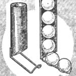 SHOP FOR BALLS
Whether you are fond of tennis, field hockey, ping-pong and a supply of balls should always be. During storage they always getting in the way, even if stacked in a box or bag. However,... CHILDREN WITH “WINDSCREEN”
The rain is not afraid of the baby, if you make a "windshield" for his stroller. You will need two separable zippers and a piece of plastic film. Design is clear from the picture. ...
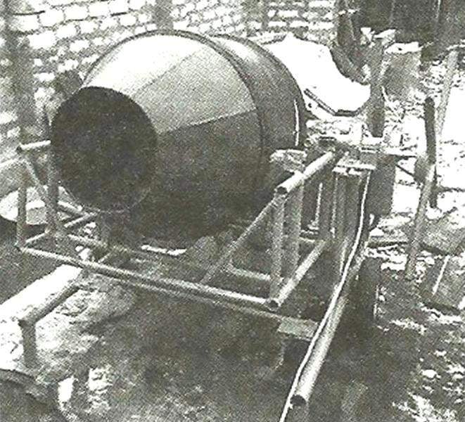
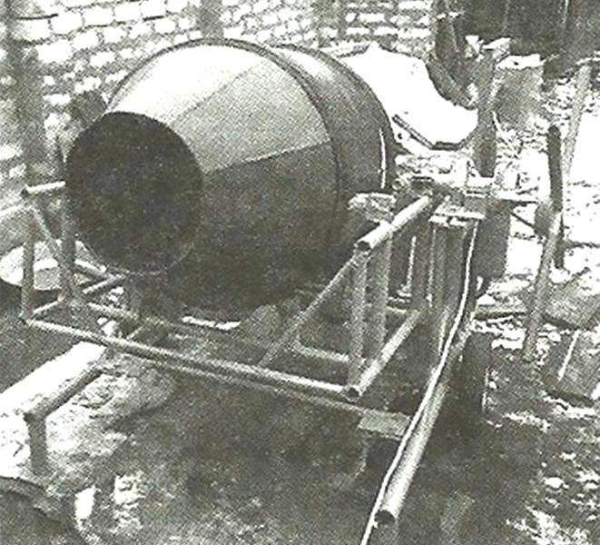 Mixer intended to receive the concrete mixture or cement-sand mortar. The performance by volume – 15 two-gallon buckets of a mixture in the ratio of 1.5 buckets of cement + 4.5 buckets of sand + 9 buckets of gravel (water not included) in one batch in for 15 minutes (5 minutes: to load, mixing and unloading). Structurally, the mixer consists of three nodes: capacity (mixer), suspended cradle, bed.