Large overload predetermine and special wing design — switching of separate plates with different orientation of annual rings (do not confuse them with the fibers — the latter only along the span). The horizontal position of the rings on the billet butt give the durability front, the vertical will help the wing be stiffer in bending.
Drank all the blanks-plate thickness of 7 mm, the second from the nose cut out and prestolite grooves for the cord. On the mandrel, glue the balsa slats that make up the external parts of the trailing edge. On a flat Board stocks by using the resin K-153 (it gathers all model) dock all blanks, except for the back plate into one. After curing of the resin wing and glue this part of the wing, then turn over his lip. Rear piping to avoid deflection, scored from three-millimeter plates, the front extends to the external tip and carries hornbeam (1.5 mm) increased edge. Ending cut from basswood, as well as a diamond-shaped cutout to a thickness of 7 mm at the axis of rocking.
Control line racing model airplane:
1 — ending (Linden), 2 — front edge (lip), 3 — front plate (balsa σ = 0,11 g/cm3), 4 — the first middle plate (balsa σ=0,11 g/cm3), 5 — second average plate (balsa 5=0.09 g/cm3), 6 — cook (propeller conventionally not shown), 7 — cap matousek (balsa), 8 — light (Plexiglas S 0.8 mm), 9 — strengthening the front edge (hornbeam), 10 — trim the rear edge (Linden, three records S 1 mm), the 11 trailing edge (balsa, seven plates S 3 mm), 12 — loop attachment of the Elevator, 13 — Elevator 14 — back plate wing (balsa σ=0,11 g/см8), 15 — wheel 16 — wheel screw (30 hgsa), 17 — motor mount (magnesium alloy MA-8), 18 — pads (S hornbeam 4 mm), 19 — under engine part (Linden S 12 mm), 20, 23 — plate of the fuselage (balsa S 20 mm), 21 — keel (balsa), 22 — crutch (OBC Ø 1 mm), 24 — strip (plywood S 1 mm), 25 — low of the fuselage (balsa S 14 mm), 26 — landing gear (D16T), 27 — the wall (balsa), 28 — wire rope automatic stop, Ø 0,6 mm, 29 — horn, 30 — pull rudder (thick balsa), 31 — axis rocking (30 hgsa), 32 — rocking chair (D16T), 33 — Cup (D16T), 34 — M2 screw of fastening of a cover of matousek, 35 — tank, 36 — cover a rocking chair (balsa), 37 — fairing (balsa), 38 — extract (Linden), 39 — bushing, fixing the rocking axis (30 hgsa), 40 — nut of an axis of rocking (30 hgsa), 41 — bushing-wheel bearing (30 hgsa).
Now for processing the workpiece of the wing. In the center it should have a thickness of 6 mm, and this size is removed at 83 mm from the leading edge. At the ends the thickness of the wing equal to 4 mm, the profile is symmetrical across the span. Having finished this work, cut the wheel height, turn over it and cut thin strips of lime. Making hog control, glue it in place, install the interior ending of the segments are slightly tapered steel tubes for the passage of the cord. It remains to penetrate the oval window for the approach to the locks pull control, enhance their contour, lime slices and make cutouts for the shoulders rocking. The model flies well and without cargo, is located on the outer end of the wing, but if you decide that without it, put near the ending of steel or brass plate weighing 5 g. the Exterior finish consists in covering the entire surface of the fiberglass with a thickness of 0.02 mm on a parquet varnish. After covering, install on both ends of the wing bamboo teardrop-shaped “skis” with a height of about 5 mm and mount all the controls.
The fuselage is going on the finished wing. The sub part of the cut of the lime hornbeam plates and reinforced plates. When it is set carefully check the parallelism of the axes of the engine and the Central chord of the wing. Depends on the stability of the flight — if the condition is sustained parallelism, the model won’t “float” in height. Now install the upper fairing, MZ hollowed block balsa and light frame-wall. Before gluing the fairing inner cavity always miss a parquet varnish. All the ends of the joints with cover and engine mount pasted a phony veneer.
The lower part of the fuselage is assembled from three plates of balsa: two thickness of 20 mm and one 14 mm. By the time Assembly this part you need to have ready the strut. The fact that it is glued in the fuselage tightly. Between the plates of balsa embedded two rectangles of plywood with a thickness of 1 mm, on which Lie the horizontal portions of the strut bracket. It’s best to glue the chassis leg with the Central plate lower part of the fuselage and the plywood reinforcements, and then fit and install the remaining two. The next step — the processing of external and internal contours of the assembled cube blanks. Slotting the inlet channels and outlet of the cooling air, please note that section they are given for the engine that has “colored” a few of the piston — cylinder. In the case of using “black” couples area of channels should be increased by 20-25% due to their width. Mine is under srebreno shirt of the motor must have a diameter of 3-4 mm larger than the shirt. As regards this part of the fuselage does not “overdo it” in the place of installation of the landing gear through the rest of the timber load from a hard landing, distributed over a large area using plywood rectangles, should be transferred to the entire structure.
When you have finished processing, get low to the fender and under engine parts, RUB it from the inside with resin or parquet varnish and glue in place, after installing steel fungi for the screws of the motor. Keel turn over Linden, the rear rail should pass along the edge of the fuselage, reinforcing the vertical tail. The specified height of the keel provides optimal Parking angle.
The fuselage and fin after pasted fiberglass joint fit engine mounts and fuselage. Then mount a thin-walled Cup that surrounds the access hole to the screw counter-piston, and fabricate a balsa cover with glazing (plexiglass with a thickness of 0.8 mm). Finally cut the plaster cast of the head of the pilot (its minimum size stipulated by the rules, equal 20X14X14 mm)- Cover legasea, her sock privertyvaetsja to Motorama one screw and the rear part includes two spikes in the corresponding holes of the fairing. Lateral elliptical window in the lid is suitable for pressurization of the cavity of the fuselage, which leaves overlay threaded carburetor for cooling the fuel tank.
After completing the exterior finish, do some fine-tuning of model elements. Fabricated from thin sheet and wire OVS two loops, hang the Elevator. The maximum angles of its deviation shall be ±20°, the course — light, without jamming and backlash. Fix the engine and the automatic stop and get to work by lowering the edge of the Elevator on the 2— 2.5 mm below the edge of the wing. Check the position of the center of gravity of fully equipped models: the optimal — 8 mm from the leading edge of the wing; it allowed the displacement of ± 2 mm. Wheel of conventional type, with the installation of measure, its vicos prevent the arrival of the device in a circle. Satisfactory results are provided by the difference between the front and rear points of the wheel, equal to 1 mm. don’t forget about the tail and the crutch. Bending his wire OVS Ø 1 mm, glue part into the fin tip.
Although each part, each node racing model require special attention, of course, the engine is the most important element. None of the other classes no such contradictory admiring imposed by the terms of the competition to the motor system. That is why equipped with a homemade motor, which in the individual production, the use of modern materials and technologies allows the model to become faster and more dynamic.
However, good results can be achieved with the serial engine KMD-2,5. However, it will be finalized. The goal — reducing the overall length of the motor and the improvement of conditions for intake of fresh mixture in the crankcase volume. These problems are solved by installing the new Zolotnik wall similar parts in the Microdrive “Rhythm”. The only difference in the treatment and applied materials. Futerko and the jet can take from KMD-2,5. When milling the walls mention that the carb needs to be located above the axis (something like if we turned the wall from “Rhythm” to 180°). This will ensure a quality intake mixture and will give the opportunity to conveniently place fuel reservoir models.
Specific recommendations for the automatic engine stop and fuel we don’t give a lot of designs of these devices, the athletes who make them, within their capabilities and experience.
The usual tank is bent from thin tinned sheet metal. Unconventionally solved only the problem of selection of fuel for a full generation. Vytachiv brass feed tube-intake, sawed it, as shown, and solder to the outer bottom corner of the tank where the advance work done corresponding hole. Napivaetsya bottom plate with round and oval holes. Thanks to them you can “adjust” the tank relative to the axis of the nozzle. The fastening screws are screwed into the mold, is embedded in the balsa plate. She also serves as a lid, protecting the rocking control the ingress of fuel and dust.
Yu. a. KLOKOV, master of sports of the USSR
Recommend to read CASE… OUT OF THE OVEN Here is not a typo: not a cupcake, namely the case — hard chemodanchik-"the diplomat". Many prefer the soft portfolio: more fashionable, and the safety of the papers, drawings and books... AMPHIBIOUS-SURVIVOR Tourist boat-amphibian "AMFA" was built by Vitaly G. Lebedev 35 years ago. Over many years of operation it is, of course, has undergone several upgrades, but inherent in it original... 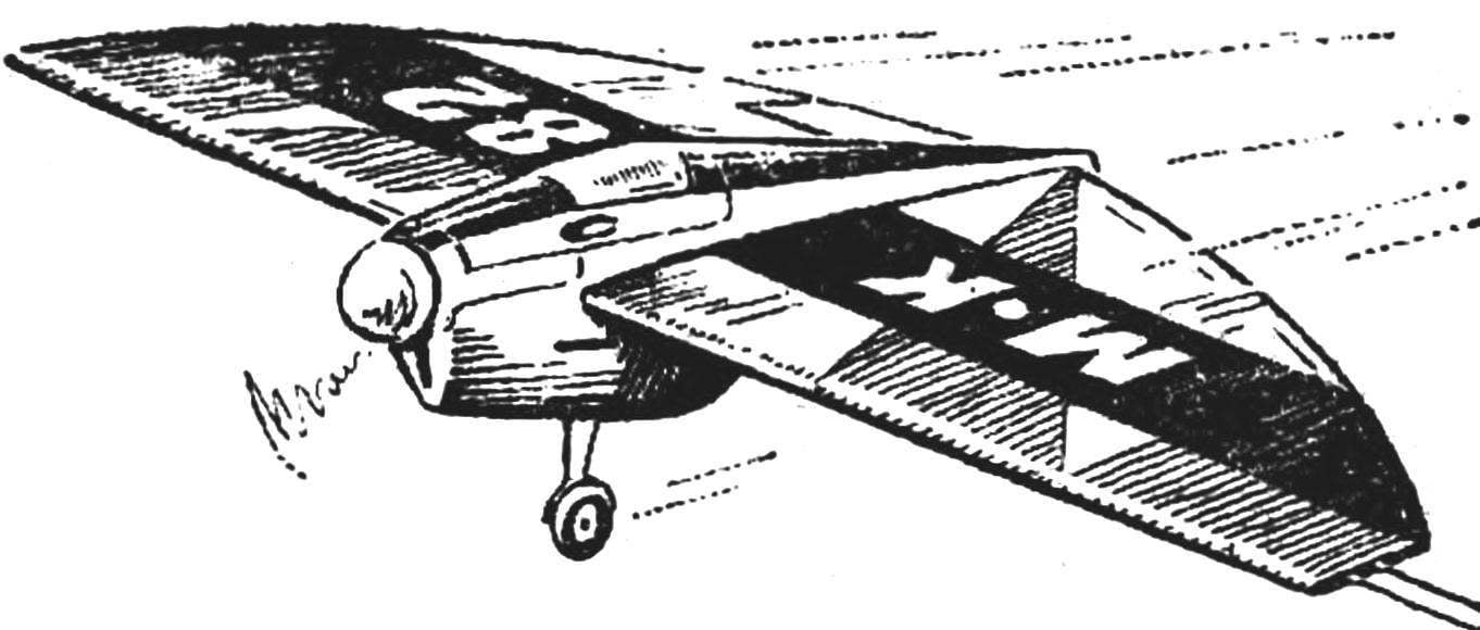
 Looking through the model magazines for the last couple of years, you’ve probably noticed a sharp change in the appearance cord racing model aircraft. They have disappeared, it would seem, absolutely necessary stabilizer. And it’s not just a tribute to another sport fashion. See what kind of patterns are models of the prize-winners of competitions of different ranks, increasingly they are flying wings. Some of the appearance of these devices, resembling a kind of pancake, not like others talking about a more modern and rapid appearance of the model. But form form and racing microplane primarily sports equipment. And from this point of view, a flying wing has many advantages over apparatus of a conventional circuit. What? First, the “tailless” much easier. Typical “representative of the” new school weighs 150 g, while an old over 220 g (without engine). So, significantly reduces the time during which the model accelerates to maximum speed. Yes, after stopping the motor it is hindered by the faster. And this win precious fractions of seconds! Less weight leads to less tension cord control. The pilot is getting easier: even at high speeds the centrifugal force is not so much to strain the hand.