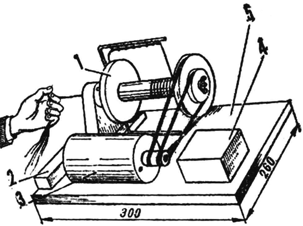
Electrocaloric (Fig. 1) consists of a spindle with a bobbin and flyer, electric motor, transformer and switch. The metal shaft of the spindle (Fig. 2) a console fastened to the rack on two bearings: with a free hand for him to put on the reel-spool and the pulley, which is secured by a nut-lamb. On the other hand the crank shaft is drilled a channel to pull the yarn and the welded flyer.
Stand — dural, coil — plastic, out of winding wires: one under her cheek machined pulley Ø 80 mm.
The flyer is bent from bar 3 mm: it is the branch with the hooks is sitepromotion guiding a yarn on a bobbin; the other plays the role of a counterweight; the distance between the branches 110 mm.
The pulley shaft is machined from plastic or metal. The bearings in the rack with the inner side of the spindle close the lid.
You must keep in mind that the coil during operation should rotate freely on the shaft, while the pulley is fixed.
Fig. 1. Elektronaladka:
1 — spindle, 2 — key switch 3 — motor 4 — transformer, 5 — stand.
Fig. 2. The spindle of the spinning wheel:
1 — shaft bearings, 2 — front, 3 — a cover of bearings, 4 — flyer; 5 — spool coil, 6 — pulley-cheek coil, 7 — shaft, 8 — nut, 9 — shaft, 10 — crank the channel.
For reliable operation of the spinning wheels the desired engine capacity of not less than 15 watts, e.g., from a video player, small fan, even from a car windshield wiper as in this design. However, you will need a small revision of it to obtain reversal, since the spinning and twisting of thread the shaft must rotate in different directions. For this purpose the engine should be disassembled, to withdraw the separated ends of the brushes and shunt windings and to mount according to the diagram (Fig. 3).
Transformer — TF-90. From his down-winding made several conclusions: using the switch S2 in five points, you can optionally change the speed of rotation of the coil. Switch S1 spinning wheels for ease of reference, it is better to put large wide key.
In the beginning, before starting to spin, skip strong thread length 30 cm via crank shaft duct of the spindle, the flyer hooks and fasten it on the reel. Run the spinning wheel and grab the thread beginning with coats, pulling her to a certain thickness, serve to the inlet and watch carefully so that the twisting was uniform. For sequential filling of the bobbin along its entire length when it’s time to throw the yarn from hook to hook. With the acquisition of skill gradually increase the rotational speed of the engine.
Fig. 3. Electric scheme.
Fig. 4. The pulley of the motor shaft.
Due to the fact that the shaft of the spindle is two of the driven pulley, the flyer will rotate slightly faster reel. This ensures that the yarn tension on the twisting plot. However, when filling the bobbin it changes, as the layer of the finished yarn is gradually increasing. So I introduced the tension PTFE pulley (Fig. 4) on the motor shaft: when “excessive” difference in rotation speeds as you fill reel belt on him beginning to slip and the tension almost all the time remains constant. Wear of pulley and belt problems.
When twisting yarn are rattling coils: with two full fill the third, having passed through the channel led the two strands. Don’t forget to use reverse by switching the rotation of the spindle in the opposite direction. You can make an accessory: a stand with a rod on which freely rotate the bobbin with yarn.
V. OVDIYENKO, Crimean oblast
Recommend to read THE BMW GOES… THE ROOF! Not so often we have to meet on city streets the car "coupe" or "convertible". However, at the dawn of its existence, almost all cars were just that — open, with soft rising tent. In the... The NETTING? NO PROBLEM! The journal "modelist-Konstruktor" write for a long time, almost from the very origin; learned a lot of useful for yourself. In response to your appeal to be not only a reader, but the...  Electrocaloric (Fig. 1) consists of a spindle with a bobbin and flyer, electric motor, transformer and switch. The metal shaft of the spindle (Fig. 2) a console fastened to the rack on two bearings: with a free hand for him to put on the reel-spool and the pulley, which is secured by a nut-lamb. On the other hand the crank shaft is drilled a channel to pull the yarn and the welded flyer.
