PROPELLER FOR WIND GENERATOR

PROPELLER FOR WIND GENERATORUnfortunately, problems with electricity occur more often, and there is no guarantee that you will pass this Cup, no matter where you live in the city or in the countryside.
To protect yourself in case of “emergency” situation, it’s best to purchase a diesel mini-power station, but… not all of it is the pleasure afford – the unit itself costs a lot, and even “feed” his need, and “oats now roads.” Another thing – the wind power. It is possible and to do that, and then – save your energy and use when needed. Many prudent owners of summer residences and personal plots do.

The biggest challenge in the Amateur construction of wind turbines is the manufacturer of the propeller. It is connected with a complex theory for its calculation. However, with sufficient for practical use degree of accuracy, this calculation can be produced using a simplified method.

Two-bladed propeller, the Profile design section


The size profile for a propeller blade with a diameter of 1 m

The projected capacity of the plant is calculated according to the formula:

N=(рFV3)/2, (W),


where R = 1.25 kg/m3 is the air density;

F — the area, sweeping the air screw, m2;

V — the wind speed, the average for the district for the year.

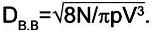
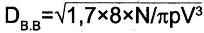
Hence the area of the rotor swept:
F= 2N/рV3,
and the diameter of the screw

Designed installation shall be designed for a capacity of 1.7 times the capacity of the generator, so

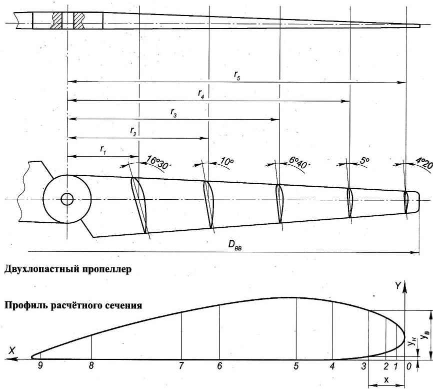
The propeller is made from wood, well-treated and not very prone to warping, such as birch or larch. The workpiece must be well-planed and dried. Its dimensions are: length — 100 mm larger than the diameter of the propeller Dвв, width 0,09 Dвв, thickness — 0.025 mm Dвв.

On the prepared workpiece from two sides are laid out longitudinal and transverse axis and applied to the transverse lines the calculated cross sections of the blades at radius r, — r5.

Three-bladed wind turbine


Three-bladed wind turbine

Three-bladed wind turbine:

1 —blade propeller (3). 2. block the blade attachment; 3—cover (2 PCs); 4—the bearing 204 (2); 5—shaft; 6—casing; 7—the bearing housing support axis; 8—reference axis; 9—nut; 10—supporting platform; 11 —bearing 203 (2); 12—bearing housing drive shaft; 13—screw M6 (12 PCs)

Tooling includes an Assembly Board and profile templates.

The stacker Board is a the same as the billet propeller, planed Board with a length of more than half its diameter 80 — 100 mm and is marked similarly to the workpiece. At the intersection of the axes and the workpiece propeller, and the Board of system of drilled holes in the stocks assigned to a pin with a diameter of 12 — 18 mm length 180 to 200 mm. the profile Templates are manufactured from plywood thickness 4 — 5 mm with dimensions of 0. 25×0. 18 RVV. Plywood blanks are glued profiles, cross-sections, drawn in accordance with table and figure in 1:1 scale. After the glue dries, cut out the templates with a jigsaw profile (hatched area) and the template is cut into two parts. To the bottom of them with nails attached to sticks with a cross-section 30×15 mm, through which profiles are installed on the stacker Board. The centers of the profiles must lie on the same horizontal axis.

The manufacturing process of the propeller is carried out in the following sequence.


After attaching the template to staple the Board to the stud is worn and the workpiece is lowered to the template, the upper edges of which are covered with paint. Next, the billet is removed and the ground left by the template prints the fetch is made of wood with a chisel width 5 — 6 mm or a round file with a large notch to a depth of 4 to 5 mm. Then the workpiece is again put on the studs for the next print. This process is repeated until obtaining the “beacon” — a continuous staining along the lines of the profiles. The upper part of the blade is handled similarly, wherein the control section is touch the top of the template manually without fixing.

As in the previous case, the edges of the templates are covered with paint.

The sample is made of wood to match the upper and lower parts of the templates.

To go to the manufacture of the second blade under the workpiece is fed a nut on the stud and tighten the lock nut, which remains so until the production of the other two blades. Thereafter, the billet is rotated 180° and the second preform of the blade. The remaining wood between the “beacons” gently remove with planers, process a file and vasculat. After that, the propeller is impregnated with linseed oil and painted several times.

Three-bladed propeller

A three-bladed propeller:

1 —the blade (birch or Linden, 3). 2—clamp (band 20×3,3). 3—pin (rod d5, 3 units); 4—fastening of the clamp (M8 bolt, 6 pieces); 5—clamp the blades (tube 42×3,5, 3). 6 Central bushing (circle d50); material of parts POS. 2-6—steel

The size of sections in calculated sections nd manufacturing of blades three-bladed propeller the same. The workpiece on each blade to 50 — 60 mm longer than the radius of the propeller.

When marking the transverse axis located at a distance of 25 — 30 mm from the edge and at the intersection of the axes of the drill hole under the pin.

Further from the end of the blade with the hole for the pin is made a thorn, the diameter of which is equal to the thickness of the workpiece and length of 1.5 — 1.6 thickness of the workpiece.

To do a spike you must very carefully, as errors of misalignment will inevitably lead to the fact that the blades will be in different planes.

Profile template

The profile template:

1 —the top section of the template (plywood s4); 2—profile (cut); 3 — (15×30 bar); 4—the lower portion of the template (plywood s4); 5—stacker Board

When machining of the propeller can be chipped or excessive selection of the wood. In this case, the defects zashpaklevyvajutsja.

The plaster is prepared on the basis of the moisture-proof glue and sawdust. Dried putty gently saw round file and sanded cloth.

At the end portion of a stud of the blade three-blade propeller drilled hole of a diameter of 0.005 Dвв to a depth of 3.5 thickness of the workpiece. Into this hole is inserted a metal pin of appropriate diameter and filled with epoxy. Finished screws must be carefully balanced.

L. CORDELIAS

Recommend to read

  • POSTWAR FIRSTBORNPOSTWAR FIRSTBORN
    "We have mastered the car ZIS-110 the machine is very complicated. Besides the fact that it requires a high level of culture of manufacture, it requires great technical maturity." These...
  • TRANSPORT FOR FORESTERTRANSPORT FOR FORESTER
    Agile, compact vehicle especially in snowy and forested areas of life-but a necessary one. In some countries, such as USA, Canada, Japan, this problem is solved by small-scale production...