
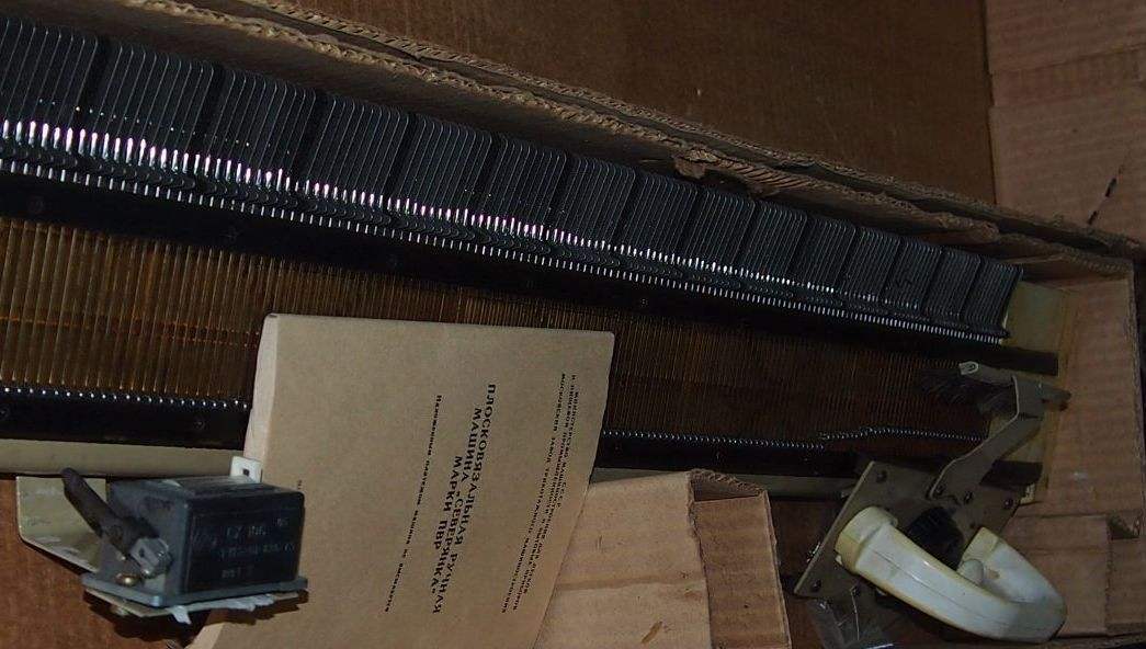
 The hostess, having flat knitting machine “Severyanka”, appreciated the convenience and time savings that it brings to the house. From a simple scarf to a beautiful dress with a complex pattern — all available to “Northerner”.
But here are the first joy associated with the acquisition and sampling, come everyday.
Many difficulties will help you to get rid of the proposed electric drive, made on the basis of the engine MU-50.
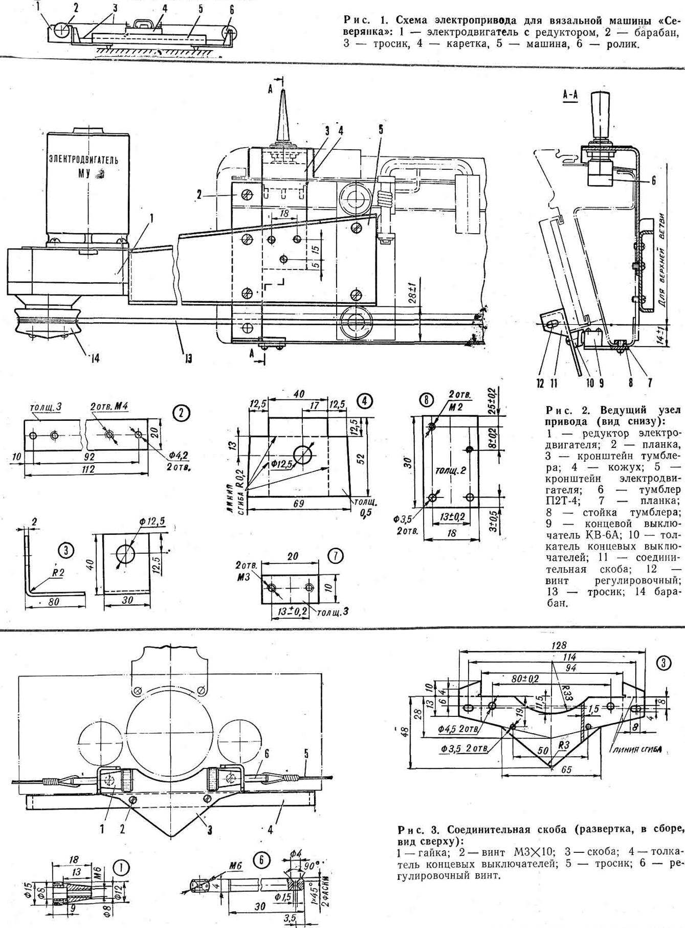
The principle of its operation is visible from the diagram (Fig. 1).
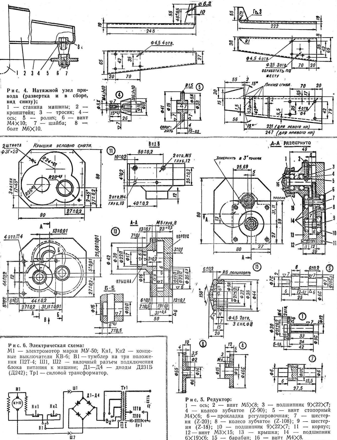
REDUCER. The execution of this most complex node requires special equipment and professional skills.
The most delicate operation — lapping planes at the connector of the gearbox. Special care requires the connection, which is performed using the pins. Best pins — needle roller bearings of Ø 2-4 mm. the gear Housing should easily separate, but mutual Emesene zastepowane its parts is unacceptable. For this purpose, the bore hole Ø 19 mm made in Assembly. Both housing halves are connected with screws МЗХ15.
If assembled, the gearbox works with the binding, figure out which pair this is happening. Lubricate the gear teeth with a thick paste of paste GOI and roll this pair. Rotate the wheels should both sides not faster than 40 to 60 rpm. do Not expose the paste in ball bearings. After running a rinse in gasoline.
The kinematics of the gearing is as follows:
i = (90×108)/(20×18) = 27
Such a large gear ratio immediately leads to the idea to use a worm gear. However, note: engine, MU-50 is very fast. Very high sliding velocity and occurs when the work load on the teeth in low efficiency of the worm gear would have caused strong heating and wear of the latter. Nevertheless, the prospect of using such a simple mechanism as a worm gear, it is real, if it is possible to set low-speed (1500-N-2000 rpm) the engine power of 40 watts.
Gears and gear — steel. Module gear both stages — 0.5 mm. Width of gear rims: the wheel 90 teeth — 5 mm, for wheel 108 of the teeth is 4 mm. Other sizes of wheels you can pick up the drawing of the gearbox. Before the final fixing of gear wheels, drill shafts to a depth of 3-3,5 mm. Drill and the ends of the set screws must be sharpened at an angle of 90°.
The pad b (its size is easily determined by the figure 5) are made of duralumin D16T sheet 1 mm thick: it will protect the bearing from dust and provide the exact position of the engine relative to the housing in the axial direction.
The DRUM 15 is machined from carbon steel. Hardness after heat treatment is HRC 40-45. The working surface it Polish.
Indicated in the drawing, the profile of the drum ensures reliable pulling of a rope that is wrapped three turns to avoid slipping when working stroke of the carriage. Tension it is selected depending on the density of the knit and in-room books … However, it should not be excessive to provide for slippage when a sudden jamming of the carriage. In between the tension must be loosened. Tension adjustment is made by nuts 1 (Fig. 3).
CABLE. You should not take the “ropes” with a diameter of more than 1 mm. experience has shown that steel cable with a diameter of 0.5 mm is working quite well even on the “heavy” modes. Preference should be given to stranded, soft. Figure 3 shows one of the variants of fastening of the ends of the cable: thread it into the eyelet of the screw 6, wrap a loop row to row of thin copper wire and sealed with tin. This will provide a very reliable fastening.
Drill the plastic side walls of machine one hole Ø 6-6,5 mm. Through them to thread the cable with screws: the lower branch it is inside the machine, the top — through the drum and the roller of the right bracket. Then both ends are fixed on the carriage, as shown in figure 3.
ENGINE. The device is actuated, as we have noted, by the motor MU-50, designed for a supply voltage of 20-30 V DC. The use of a DC motor due to the lack of compact and powerful AC motor with the AC power.
BRACKETS. To simplify the work on these details, we have given drawings of each bracket. Left of them — for the engine, to the right of the tension pulley. All sizes are, of course, correspond to the bending radii indicated in the drawing. The final markup for fasteners is recommended.
Begin Assembly should be setup at the ends of the stand (steel base of the machine) of the two slats 2 (see Fig. 2). Mount brackets to the car can be seen from figures 1 and 2. When you install make sure that the axis of the drum and the roller are parallel among themselves and perpendicular to the line of travel of the carriage. To do this, first secure both bracket clamps, set them up, after which you can available in the bracket holes to mark the screw holes in the straps 2 and the stand of the machine.
Bracket toggle switch-switch is attached to the left bracket at the top. Its exact position relative to the machine is defined in Assembly with switch and decorative cover for him. For placing the switch inside the base of the machine in the front panel to cut a window.
SWITCH. The most suitable for the switch of the carriage and turned the switch П2Т-4. It is designed for currents up to 6 A, which corresponds to the starting current of the motor MU-50. Before installing a toggle switch on the machine needed some “improvement”: has to be installed in a second return spring to both his working position was not fixed; for convenience, it is better to build up his pen.
THE LIMIT SWITCHES. To stop the engine at the approach of the carriage to the extreme provisions applied micro KV-6. The method of installation is seen in figure 2.
10, the pusher acting on the button of the limit switches, can be made of textolite strip of cross-section 10×10 mm pushrod Length 190 mm.
THE POWER SUPPLY UNIT. The power transformer Tr is executed at the core of sh25, the thickness set to 50 mm. the Winding of I contains 530 turns of wire sew 0.57 mm and 330 turns of wire sew to 0.69 mm. Secondary winding II contains 85 turns of wire PEV 1.0 mm and has taps, since the 70-th round, every 5 turns; this allows you to get the voltage In steps 25-31, using 2 — to change the speed of the carriage.
The rectifier diodes applied Д231Б or Д242.
All installation wiring is best done with a wire mgshv-1,5. The wiring should be placed inside the machine, using the screws.
R. PETROV, engineer
Recommend to read
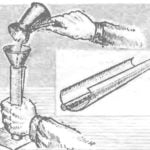 FLUX PENCIL
When finished, do not rush to sweep away the iron filings: putting them on paper with the help of the charge from the back of the magnet and adding rosin, it is possible to make flux for... WALL-HEADSETS
Children, living room, office, bedroom... How many rooms in the apartment? One! — according to our regular contributor and consultant Victor Strashnov. Thanks to them the...
