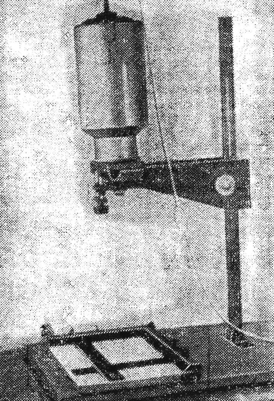
 The device, which we advise you to do, simple and affordable to manufacture a wide range of novice photographers, especially those who love tinkering. The appearance of a photographic enlarger is in the picture and the figure. Its main elements are: base, rod with reference fifth, sliding bracket, a lens with a focusing device and a housing of illuminator.
Base 400X500 mm is cut out of chipboard or plywood with a thickness of about 15 mm. On the lower part makes sense to consolidate the four rubber feet.
Rod is a steel pipe with a diameter of 25-30 mm. Its length is 750 mm, which provides a maximum print size of 18X24 cm. rod is Fixed on the base by means of support feet of any structure. The only restriction is hard without play communication with the base.
Mobile bracket is constructed from two plywood cheeks with a thickness of 10-15 mm (‘size — 350X120 mm), two parts, resembling prisms metalwork, clamping screw with nut and table, on which are mounted the illuminator lens and a negative frame. All parts are collected on casein or polyvinyl acetate glue and screws. The dimensions of the table are selected in accordance with the dimensions of the housing of the illuminator and focusing system.
A focusing device is a “harmonica”, glued together from black leatherette or laterina. On one side it is attached to the table (after it is cut a hole Ø 55 mm) and the other to mobile a plywood Board on which is mounted a lens with a focal length equal to 50 mm. do Not worry if you fail to get hold of, in a pinch you can substitute the lens from overhead projector, or even with a pair of plastic lenses that are sold in stores for stamp collectors.
Focussing is carried out six-millimeter adjustment screw with a large knurled plastic head. In mobile fee are pasted two metal guide sleeves — cuts tubing of suitable diameter. The sled, which they move made of metal studs-bars, ending with both ends threaded. Bottom skids combined dural crosspiece with two screw (M6) and one smooth hole. The table slide or are fixed two nuts, or just tightly inserted into a pre-greased with glue holes. Sliding nut, which includes an adjusting screw with an interference fit is inserted into the hole on the circuit Board and is fixed with a washer, cut from thin plywood and glued to the Board. Mobile circuit Board hole for the lens is cut so that the thread when screwing in the cost of the lens formed in the threaded groove plywood. Then the lens “sits” into the Board tightly and without the use of additional fasteners.
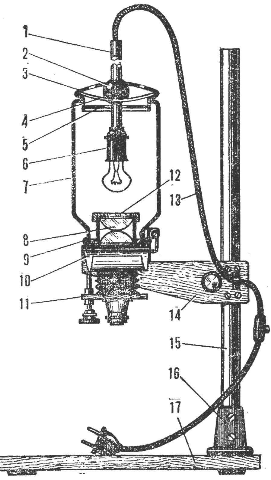
Appearance improvised photographic enlarger:
1 — tube, 2 — ball hinge, 3 — cover, 4 — spring, 5 — light drive, 6 — holder, 7 — housing of the illuminator, 8 — condenser, 9 — adapter ring, 10 — negative frame, 11 — focusing device, 12 — frosted glass, 13 — cord with switch, 14 — mobile bracket, 15 — bar, 16 — support foot, 17 — basis.
The body of the luminaire made from aluminum cans. It is best for this purpose is a vessel with a diameter of about 150 mm and a length of 220 mm. the bottom of the cans carefully cut out the diameter of the cover into the hole it should go with some interference. In the lid for ventilation, holes are drilled. The Central hole intended for the fixing of the hinge, which is passed through a holder tube holder — steel tube Ø 12 mm.
The hinge holder is a metal or plastic ball Ø 30— 40 mm. To the lid of a can he is pressed by a spring-steel bracket — a piece of wire, bent in the shape of a rectangle. Order through the ventilation holes did not penetrate the light cover of the bottom is closed up dural disc with a Central hole. To adjust the position of the lamp is necessary to provide movement of holder inside the ball.
For uniform illumination of the negative is best to use a condenser lens, positioned in the throat of a can. For this enlarger it is best to use lenses Ø 50 mm, having their convex sides towards each other. But in principle you can do without the condenser.
The negative frame is cut out of tinplate with a thickness of 0.8 mm or aluminum with a thickness of 1,5—2 mm. Both parts are connected by hinges. In the centre is cut a rectangular hole 24X36 mm. film Guides (4 pieces) are cut from sheet aluminum of a thickness of 3 mm in the form of the letter “T”, are inserted into hole 3 mm Ø and clench.
It remains to collect the photographic enlarger. First to the base by two or four screws is attached to a basic heel, and it is inserted into the rod. After that, the table movable bracket on the hinge, riveted to the neck of the can, is attached to the housing of the illuminator. The position is chosen so that under it was a part of the negative frame, and the body needs to take a strictly vertical position.
Then in the neck the lenses of the condenser and frosted glass. Apparently, it does not dispense of transition rings that can be cut from either plywood or aluminum.
Now you are ready to test the device. Insert the frame in the negative film and turn on the illuminator. Focus the image. If the negative is illuminated unevenly, locate another position for the lamp. Carefully inspect the included magnifier in the dark — it should not break out of the rays of light.
Recommend to read
 FROM PIGGY CRAFTSMEN
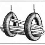
The lumber before use is recommended long to dry. In the traditional laying on the ground, it is difficult to protect them from moisture, and in the premises because of their size, they...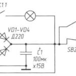 THE LIGHT IN THE BATHROOM
It often happens when someone from the household forgets to turn the lights off in the toilet — he may be there without the use of a lot of hours. A simple automatic device which, when...
