“THERMOS” FOR POTATOES

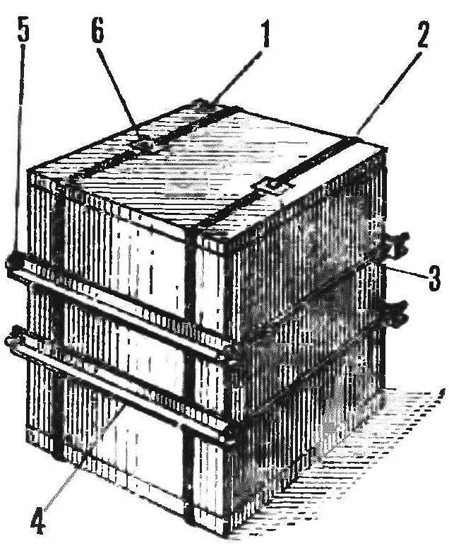
For the fourth year keep the potatoes on the balcony in a container of foam slabs of size 900X 900X 90mm, strapped together by means of aluminum corners section 25×25 mm and length of 950 mm and steel pins ø 8 mm (Ø = 950 mm). At the ends of the studs is threaded M8. In places the joints are glued shopon thickness of 5-8 mm for sealing. The cover is pressed against the two lever locks and can be removed. Locks mounted on two metal bands spanning the box around the perimeter (Fig. 1).
Heater are two connected in parallel incandescent lamps for 230 V, 25 W, suspended in the center of the cylinder 0 120 mm, length 800 mm, made of aluminium sheet with a thickness of 0.8 mm.
 
Fig. 1. The appearance of the container
Fig. 1. The appearance of the container:
1 — slab of foam plastic, 2 — metal strip, 3 — pin ø 8 mm, 4 — corner 25 X 25 mm, 5 nut M8 6 — castle.

 
Warm light air rises up the pipe and coming out of it, evenly distributed throughout the volume circulating inside the box (Fig. 2).
 
The temperature sensor is a thermocouple SCI-5071, which is the measure of reduction of potato is gradually lowered. The device connected to the electronic controller temperature) RT-2 installed outside the “potato”, for example, in the bathroom, the kitchen.
 
Fig. 2. Thermostat
Fig. 2. Thermostat:
1 heater (filament lamp), 2 — металлическиq cylinder, 3 — potatoes, 4 — sensor, 5 — direction of air circulation.

 
About the operation of the heater via the control light ÌÍ2,5ВХ0,15A, to which is connected a resistor of about 25 Ohms. They are included in the circuit of incandescent lamps and located next to the temperature controller (Fig. 3).
 
Fig. 3. The electrical circuit of the thermostat.

 
To ensure correct working of the heater and the potentiometer RT-2 turn in the direction of increasing temperature. The device is activated, the control lamp lights up at 2.5 V, indicating a faulty bulb. Then the potentiometer is returned to its original position.
 
Fig. 4. Schematic diagram of the temperature controller
Fig. 4. Schematic diagram of the temperature controller.

 
If you are not able to get the temperature controller RT-2 and TSM sensor, collect the thermostats themselves for one of the circuits published in Amateur radio literature, for example, the book N. Decorative plaques “Automation of home” . The device is designed to maintain the temperature with accuracy of ±0.1° C.
 
Schematic diagram of the thermostat shown in figure 4, its circuit Board with the layout of the parts in figure 5. Diodes VI — V4 of the rectifier bridge are mounted on the radiator made of aluminum plates with thickness 2— 3 mm. Radiators attached to the plate (Fig. 6) made of a dielectric material (Micarta, vinyl, Plexiglas, plywood) with a thickness of 3-4 mm.
 
Heating element (filament lamps with a power of 50 W) through a socket XI, x2 (Fig. 4) included in the circuit of the thyristor V5. If flowing through the thermistor R6 current creates rigged the resistor R7, the voltage drop is greater than 1.2 volts, transistors V8 and V9 are opened, and the V6 is closed, the current through the thyristor V5 heater leaking will not. As the cooling of the thermistor its resistance increases, resulting in a decrease in the voltage on R7. When it falls below 1.2 V, the transistors V8, V9 closed
are. The current flowing at the beginning of each half-cycle through the resistors R2, R4, opens the transistor V6 and the associated thyristor V5 — heater begins to work. After increasing the temperature the resistance of the thermistor decreases and the heater switches off.
 
Fig. 5. The circuit Board of the thermostat with the layout of the parts.
 
Thermostats can be assembled on any series of transistors KT315, КТ312, in which the current transfer ratio of not less than 50. Diodes VI — V4 is designed for direct current of at least 3 and the reverse voltage of 400-600 V. the Thyristor brand КУ202 must withstand a maximum direct voltage of at least 400 V.
 
The thermistor R6 is any of a series of MMT, CMT or CT. Its resistance at 20°C is 50—
200 kω. Depending on the parameters of the thermistor rigged to choose the value of resistor R7, the value of which should be approximately two times less resistance thermoresistor at a temperature of 203 C.
 
Fig. 6. Radiators for diodes
Fig. 6. The heatsinks for the diodes
 
To set the desired temperature near the thermistor, a thermometer, and a regulator R7 transferred to the top position on the scheme. When the temperature rises to the desired value, R7 the handle slowly rotate in the opposite direction until you turn off the heater.
 
The thermistor is placed in a thin insulating tube and, together with the insights filled with epoxy compound.
 
E. BABYNIN

Recommend to read

  • CORKSCREW FOR BEARINGCORKSCREW FOR BEARING
    How diverse is pressed in units of parts so numerous and adaptations for wheel — pullers. However, the majority of them operates on the principle of ejection. Well, if the part is...
  • THE DOORS ON “AGRIMONY”THE DOORS ON “AGRIMONY”
    Maybe a good ball or a magnetic latch for Dvorak table, painfully slamming when closing-opening. I propose a simple and quiet option: use widely used in clothing sticky Velcro...