Basic details
(Approx.: you can use any other similar parts)[email protected] — 7770RPM — 1080 grams per motor (thrust)
Frame parts
I still like the Central part of tricoptera the first version and each gladly cut me some on a CNC machine.
You will need 10 pieces M3x16 mm screws.
And three beams of the same length. I cut the 48cm rays 10×10 mm pine.
Openings in the front beams drilled 25mm in from the edge. This is more than was planned in the procurement, but the extra material adds strength to the entire frame, like a little piece of wood in front long 40mm.
It’s time to twist it all the M3 nuts with fixation. Arrange the beams before tightening the nuts. The rays must touch the bolts in the unfolded state. Be careful and do not over tighten the nuts, but they have to be tightened to hold the beams during the flight. Well, that finished the main part of the frame.
You can also use a simple center piece. At the same time it will come in handy if you have to hang a lot of equipment. Just draw a basic drawing in the corners and will be easier to slice if there is no CNC machine, as all the lines are straight.
Speed controllers
Time to “fix” the speed controller. Remove them from the heat (be careful not to damage the insides).
Remove all wires (except 3-wire) with two speed controllers, and the third and leave the power wires. This third Regal will be on the tail and it just so happened that length just enough. (Approx.: check if you have enough length with other speed controllers).
Use 16AWG cable, to lengthen the wires. So I recommend to solder the connectors for the motor. And use heat shrink to protect the set from dust and dirt.
It’s time to solder all the power wires together. Not to worry when soldering — wire wrap wire, it will help to keep them together.
Solder the power connector and you’re done.
Programmable speed controllers. I used the card for programming and such settings are appropriate for my speed controller. (Approx.: do not have to use the card to program the controller, you can use the instructions in your manual for controls).
Swivel mechanism
It is time to swing the rear of the motor. Here is the bag with the 40mm mounts for the front wheels. Only 2.5$ for a half-unit rotation.
Take two such thing and drilled one hole of 4.2 mm.
Remove any debris after drilling and insert a 4mm axle (approx. for example, a carbon tube from a fishing rod). It clearly establishes in the part that was not drilled. Will have to try to insert one into the other.
Saw off excess. I used a Dremel with the disc.
Grind the bumps on the part that was drilled.
It’s time swivel mechanism servoy. Used servo came with cross mount, which should do nicely.
Make the spider flat.
And tape to the steering mechanism, then it is easier to drill, and to stay stronger. A couple of important things: the spider sticking to the part that was not drilled and try to hole coincides with the position of the shaft. If you fail, there will be extra load on the servo.
Now drill two 1.2 mm holes. Drill slightly deeper than long screws, which will then bond it.
And secure with screws, for example from a small servo.
Cut away the excess.
Mounting DT750 very well suited for such a mechanism. Only have to drill one hole in the steering mechanism, which will be strengthened motor (where bolted cross from the servo).
Three 2.5 mm ties all that is necessary to secure the motor. Ties better to fix as shown in the picture to not interfere with the deflection of the rotary mechanism.
And now a little remake the servo, cut the bottom part of attachment. To the servo to match the height, need to add 0.8 mm of fiberglass or grind the swivel mechanism on these 0.8 mm.
The rotating mechanism is ready. It remains only ties to fasten it to the rear beam.
The servo draw thicker ties. When installing the ties make the ties castles were on opposite sides of the beam.
Motors and Assembly
Begin to solder the connectors to the DT750 motors. I love DTшки. They are quite efficient, have high torque. This means that the propellers will be able to quickly change the rotation speed and tricopter will be more stable and have a good response. Also, I like the 4mm threaded rod, without extra fasteners to install the propellers.
But the weak point of these engines at the connection of the wires with a winding. If you are going here and there to wiggle the wires, it is likely that they will simply fall off. To correct this and make the engines more durable — secure this place with epoxy.
The motor shaft protrudes slightly from motormount, so I made a small indentation in the beam to prevent friction. The friction motor on the beam will cause excess vibration, so the easiest and fastest way to do is make a small indentation with a drill.
Attach the motor coupler 2.5 mm to the beam. Simple, cheap and fast. And it will save the motor during the collision with the ground/pavement, etc.
The axis of the motors is too long, which adds to the risk of damaging the motor in the fall (and vibrate more). I cut off the excess, leaving about 21mm, it is enough for GWS propellers and bolt.
Now put the engine in place. Always use something to secure the bolts, from vibration otherwise they will spin in flight.
Install the rear motor so that the wires were perpendicular to the beam, then they will not cling and RUB against the servo.
Landing gear is fixed with zip ties and propeller installed on the motor. The propeller will have to counterbore 4mm. Use the special bolts to the propeller fell off.
Set the speed control and extension cord for servo.
This tail rotation mechanism has low friction and fairly durable. The servo mounted vertically, so not much to disturb the flow of air from the propeller. I like the direct drive servo when there are flimsy and unnecessary details.
Depreciation of the camera and flight controller
It’s time to talk about mounting the batteries and the camera (approx. next, I will call it a suspension). To prevent vibration I used 2 cut silicone tube for 38mm (approx.: the fuel hose or tube for aquarium pet store). 8mm outer diameter and 3mm inner.
I used 2.5 mm ties (suddenly!) to secure the tube on the suspension.
The suspension is attached from the bottom all the same 2.5 mm cable ties.
I still like Kapitanchuk (KK) controller you can buy anywhere (approx. better yet, buy for example or other MultiWii flight controller with auto leveling the horizon).
To attach the flight controller, I used the squares from several layers of thick tape. Just mount them on it and the frame.
Add battery and ready to fly.
The frame is assembled. Quite convenient for transportation.
I hope the translation is like, actually the translator from me so — so- at school and University, barely passed tests/exams
Where to find parts?
Most of the parts you can buy on the website hobbyking.com and not bad to save money using this site with buddy codes for discounts.
Full list of parts and possible replacement
What is meant by substitution personally put on your tricopter.
Name Minimum quantity Used in the article Alternative Motor 3 DT750 750kv — $11.60 KDA20-22L — $14.72 Speed controllers 3 TURNIGY Plush 18amp — $11.90 HobbyKing 30A BlueSeries — $10.47 (actually 30A is too much) Servo 1 BMS-385DMAX — $20.48 BMS-621MG — $23.80 (was very large, not recommended) Propellers 3 GWS 1047 — $4.82, or GWS 1147 — $5.76 10×6 — $3.48 or 11х4.7 — $5.98 Batteries 1 3s Turnigy 25-35C 2200mAh LiPo — $8.99 Turnigy nano-tech 2200mah 3S 25~50C Lipo — $17.99 Flight controller 1 HobbyKing Multi-Rotor Control Board V2.1 (Atmega168PA) — $14.99 Crius MultiWii Lite — $47.52 (actually analoginiu, but the sensors separately, the Arduino separately) Details of the rotary mechanism 1 Front Wheel Steering Arm & Mount Set 40mm (5sets) — $2.59 The rest A lot of things to need, such as bolts, nuts, cables, glass fiber for frame, beams made of aluminum or wood, but it can be found in nearby stores or on the same hobbyking.com TOTAL $122.37 — $123.31 $170.95 — $173.45
To this price you need to add delivery charge and take away the discount, which you can get here .
Of course, tricoptera need another equipment for control and battery to it.
At ideo:
VIDEO
Recommend to read THE MILL… ON THE TABLE Regular readers of our magazine and viewers of the television program "This you can" know the name of the craftsman from the suburban town of Troitsk Yury Mikhailovich Orlov. Designed... Garden sofa Mankind has made and described a huge number of the most diverse garden benches. But two reasons did not allow us to take advantage of centuries of experience: the absence of special... 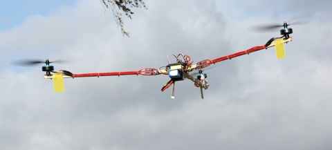
 I spent all summer with her son, a soldering iron and Arduino IDE, not in the field with a copter, so now my free translation of article Swede David Windscale (David Windestål, I hope correctly wrote) about the construction of tricoptera — stone with three engines and a rotary mechanism to compensate for the rotation and control the rotation. (please do not walk unnecessarily on the site of the original, as he often falls Habra and under the cut a lot of images).