“M-K” № 7, 1980 . The description made the cell, and it has become a necessary tool in my workshop.
Soon, however, the design was disappointing. Large (20 kg) mass of the cell, almost the same — a power source sufficient for some works performance, rapid heating during operation, the voltage at the non-insulated electrodes, the constant leakage of the electrolyte through the joints, foaming and ejection of the electrolyte in the shutter and the burner, the rapid dissolution of the electrodes, all these deficiencies had to be eliminated.
The result was a design, free from these disadvantages. The proposed electrolyzer has been working for many years with no complaints. The design is quite simple, and the repeated relief achieved by reducing material consumption (except for electrolyte).
Camera like many of my friends and acquaintances, made a few more copies (called my “torches”: the name stuck — probably because it’s easier to pronounce) various capacities — from 200 to 500 l/h gas mixture. Requests to help in the manufacture of the cell continues, and I decided to write in your journal.
The device of the cell
The main part of the cell — body 1 (Fig.1) lined inside with a dielectric 2; includes internal electrodes 5, separated from each other by rubber rings 12. At the ends of the hull mounted flanges 3 with terminal electrodes 6, a sealed current leads 7 and 4 fittings. Flanges 3 of the transparent (plexiglass) and slots on the edges of the terminal electrodes 6 are used for visual control of the level of the electrolyte and the electrolysis process.
The electrodes are made of stainless steel that do not dissolve during operation of the electrolyzer. Since the internal electrodes do not carry the technical load not acting as a heat sink and does not dissolve during operation, they can be manufactured from very thin material — foil with a thickness of 0.05…0,2 mm.
All electrodes 5 consist of two holes 11 in the top for gas outlet and fill the electrolyte. At the bottom of the electrodes to make the holes impossible, since they dramatically impair the functioning of the cell, shunting the electrical circuit of cells and causing “pumping under pressure” of the electrolyte to the output fitting. A cell with such electrodes (with holes at the bottom) heats up quickly; occur and emissions of the electrolyte through the outlet.
The electrodes are separated by a rubber ring 12 is of rectangular cross section. Ring outside diameter slightly larger (by 1 or 2%) of the inner diameter of the cell, which during Assembly provides a sufficiently good integrity of cells without the use of sealants and prevent the overflow of electrolyte when the slopes of the cell.
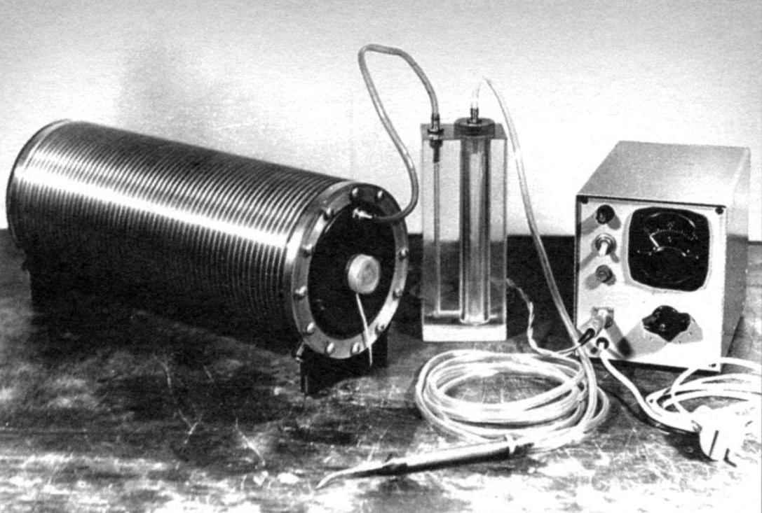
The fittings 4 are used to fill electrolyte, water and removal of produced gas mixture. When working one of the fittings is closed by a plug 10. Supply power voltage to the end electrodes is made through a sealed current conductors 7. On the flanges, they are covered by the insulating covers (Fig. 1, see photo). The bushing (Fig. 3) with an interference fit is mounted on the nut, fixing the current lead and it is screwed on cover.
Manufacturing unit
The proposed description and drawings relate to a variant of the cell capacity up to 200 l/h of a mixture of oxygen and hydrogen.
The housing 1 (Fig. 1) of the cell are manufactured on lathe wall. Housing material — aluminum alloy brand Д1Т, D16T, АК8Т. Axis M4 threaded holes in the ends of the shell for fastening the flanges should be the same.
The insulator 2 of the body is an important part of the cell, since it ensures the safety and protection of the body from the electrolyte. It is made of sheet material 1 mm thick (if thicker, then you have to adjust the dimensions of the flange and of the electrodes or housing). As insulator can be used for sheet rubber, plasticized vinyl, polyethylene, PVC. From a parent sheet coils pipe length 420 — 450 mm; butt welded using any available method (e.g., heating both edges throughout the length of the ribbon heater, followed by compression into a custom fixture). You can just using a soldering iron, through the separating strip of the film of Dacron or PTFE, so that the molten plastic does not stick to the tip of the iron.
Fig. 1. Electrolyzer:
1 — housing;
2 — insulator;
3 — flange;
4 — fitting;
5, the inner electrode;
6 — terminal electrode;
7 — current source;
8 — electrolyte;
9 — stand;
10 — end cap fitting;
11 —holes;
12 — rubber ring.
In the manufacture of the insulator rubber must be combined with the raw rubber and vulcanizer. Vulcanizer homemade from aluminum bar on the entire length of the joint.
Procurement of insulator should be of such width that the diameter of the resulting pipe was larger than the inner diameter of the casing at 1 — 1.5%. Pipe insulator is inserted into the body with equal overhangs at the ends. These protruding ends have a plastic pipe together with a part of the body, heat in boiling water and after softening wrap on body (rubber heat, of course, not required). Fit and plumbing pipe made from polyethylene with a diameter of 110 mm. be aware that aluminum alloys react violently with alkaline solutions, so the tightness of the isolator should be guaranteed.
The flanges 3, the plugs 10 and caps for current leads made of sheet of Plexiglas 10 mm thick. Flanges are polished to a high transparency.
Fittings 4, electrodes 5 and 6, the current leads are made of stainless steel 12H18N9. Electrodes 5 — foil, hand-cut with scissors, followed by set them on a lathe (or without processing, if they are cut very carefully). The number of electrodes 110 PCs. Holes in the upper part of the electrodes are punched using a simple stamp is taken steel strip with thickness 2 — 3 mm, and size 20×60 (steel u7) and bent in half with a gap of 0.2 — 0.5 mm. In the plate is drilled a through hole with a drill bit diameter 6 — 7 mm, after which the plate is quenched. Instead of a punch you can use a sharpened shank, chosen so that the drill was part of the stamp as possible with a smaller gap, but not tight. The holes in the electrodes are of good quality, no jagged edges and burrs.
The end electrodes 6 are mounted on the flange using the current leads 7 and low nut M8x1. To seal in the groove on the flange installed rubber ring. Fittings 4 flange — also with rubber rings for sealing.
Stand 9 out of any plastic: they are mounted on the housing so that the joint of the insulator was at the top.
All internal parts of the cell before Assembly should be well washed with hot water with soda.
After installation of one of the flanges the installation of internal electrodes. This is done so. The housing is mounted vertically, the electrode is lowered and is guided in the housing (for example, using a thick knitting needle). Then lowered rubber ring and pressed to the electrode with a special device. It is a disc of thick smooth plywood with diameter equal to the diameter of the electrode; in the center is attached a long (300 — 350mm) wooden round handle. In the disk there should be holes for the passage of air. After installing several rings and electrodes need them with the power of “compacted”.
At the end of the installation checks the integrity of the cell in the bath water: is pumped with air pressure 1.5 — 2 kg/cm2 from a car pump. Integrity must be complete.
Before pouring of the electrolyte with both fittings removable end caps: electrolyte necessary to fill the entire volume of the cell. After pouring the machine is in working condition. The fittings put on the rubber tube and the ends of their drop in three-liter glass jar. Connect the electrolyzer to a power source. Increase the current up to 4 in steps of 0.5 And aged for 3 to 5 minutes. The escaping gas will make the cell with formed foam residual dirt on parts. Maximum operating current is 3.5 A.
During normal operation of the electrolyzer, the electrolyte level when the current is switched on, rising only a few millimeters without foaming. If it is formed and when the work is removed from the cell through the fitting, replace the electrolyte with fresh and repeat the operation preparation of the electrolytic cell to work.
For the preparation of the electrolyte used, only pure sodium hydroxide and distilled water. The concentration of electrolyte 10 — 20%.
Prior to operation, and periodically during use of the apparatus, check the insulation resistance with a megger at 500 V (or at least a tester at the limit of measurement IOM). The insulation resistance shall not be less than 0.5 Mω.
The power supply can be performed on the thyristor or autotransformer with a stepped current regulation with iron, designed for 120 — 150 VA capacity.
Main technical data
Gas output at maximum power, l/h…………………………200
Power, adjustable, W……………………….up to 700
Water consumption at maximum performance, g ……….107
Weight of cell without electrolyte, kg…………………………………4,4
with electrolyte, kg………………………………………………………………….7,0
Dimensions, mm…………………………………………………………..380x160x140
I. Popov, Kuibyshev
Recommend to read SIX CLONES “KARL” Mid-1930s, the Political leadership of the fledgling Germany wants revenge for the defeat in the First world war. The command of the Wehrmacht, forced perevooruzhit the army requires a... PIŁA-PENDULUM Arsenal machine tools home workshop, it is useful to fill up the circular saw. Pin CE on the workbench, next to the plumbing Vice, in which clamped the workpiece. Working tool saws —...
 I’m a longtime subscriber of your magazine, use a lot of printed in it. I especially liked the article “Fire… of water”, published in “M-K” № 7, 1980. The description made the cell, and it has become a necessary tool in my workshop.