In the engine compartment located engine (15) from the GAZ-21 with the clutch, transmission (17) from the car “Victory”, a homemade transfer case (19), a winch (68) and other units of the power plant and transmission. It all closes legkoatleticheskiy the hood (16).
As for the engine, first I put from the motorcycle IZH-49 with a capacity of 10 HP Converted it into the water, but the speed of the boat with him were only 15 km/h. This state of Affairs didn’t suit me, and decided to buy in a thrift store for 75-strong “volgovskoe”. Made for him and radiators: oil (65) and water (30) with lobe pump BNK-12 (64), on the exhaust manifold welded with water cooling (48). The pump drive and electric fan oil cooler is carried out by a belt from the flywheel of the engine. Tests showed that this version of the amphibian can reach speeds on land of up to 25 km/h and on water is up to 55 km/h engine Power is enough to tow a water-skier and remains a small margin.
As a mover used bronze propeller (outer diameter 440 mm), mounted on a hinged corner column. Torque transmission from the drive shaft using a split Cam clutch and built-in speaker enclosure gear composed of two bevel gears (і1=0,55, і2=1). For the first used gear from the rear axle of the car GAZ-51 (the side z1=20 and z2 sat= 11) and the second pair of gears (z3=z4=17), made of steel and cemented 12ХНЗА. And the first (upper) pair of washed butter, cooled by seawater passed through the built into the sump of the column coil. Reducer column irreversible, so the water used is straight and reverse gear manual. When reversing to avoid tilting the column up it is locked with a special lock. Control arm locking mechanism made for the post of driver.
Fig.1. The layout of amphibians (from the top view, Fig.24 shown in a lowered position, POS. 11 and 16 conventionally not shown):
1 — coil bow-steering, 2 — wheel retaining cables (steel, Ø4,5), 3 — headlight, 4-lifebuoys, 5 — roller, 6 — coil control wheel, 7 — shield the instrument from the car Pobeda M-20, 8 — fire top-end, 9 — rear view mirror. 10 — coil steering, 11 — glazed cabin (Plexiglas, sheet, s8), 12 — seat removable, 13 — BIMS (D16T. area 30×30), 14 — cranes water, 15 — drive, 16 — hood engine compartment 17 — transmission (KP), 18 — shaft (GAZ-69), 19 — box transfer case, 20 — coupling rubber, 21 — node bearing 22 — lift bracket tilt speakers 23 gear steering worm gear, 24 — column folding, 25 — intakes, 26 — lamps side, 27 — transom plate (foam), 28 — wheel (660×220), 29 — battery 6ST-55, 30 — radiator water. 31 — redan, 32 — turret roof in folded position (D16T, leaf ), 33 — pedal 34 gear turn the wheels with tool tray, 35 — wheel (300×125), 36 — shaft (30KHGSA, rough 35×2,5), 37 joints, 38 – bulkhead hermetic, 39 — the hatch of the forepeak, a 40 — lanyard, 41 — control devices of the engine, 42 — arm differential lock, 43 — arm choke carburetor 44 – lever latch “gas”, 45 — gear lever, 46 — the ignition lock 47 — gas tank (volume of 22 l), 48 — cooling jacket of the exhaust manifold, 49 — couplings, 50 — lever differential lock, 51 gear wheel, a 52 — differential 53 — sprocket z=18 (from the motorcycle IZH-59), 54 — drum brake, 55 — silencer, 56 — control cable front wheel, 57 — winch cable, 58 — speed indicator (lag), 59 — toggle-column lift, 60 — arm fixation of the column at the reverse, 61 — duck, 62 tubing air peredannoe space (4x), 63 — hook, 64 — pump BNK-12, 65 — oil radiator, 66 — gimbal (motorized FDD). 67 — shaft coupling (30KHGSA, steel 30×7), 68 — winch, 69 filter water.
Fig.2. The clamping wheels (left):
1 — clutch coupling (steel 30KHGSA), 2 — pins (45 steel, rod Ø8), 3 — shaft coupling (steel 30KHGSA), 4 — bearing 7000106, 5 — screw M5 body mounting cuff, 6 — trim the boat, 7 — fairing (foam), 8 bolt M6 mounting fairing, 9 — adapter (steel khvg), 10 stop (screw M6), 11 —disc wheel (Д16ТВ), 12 — bolt M8, 13 — starbolt М16х2 wheel fixing (steel 30KHGSA), 14 — driveshaft (steel khvg), 15 cuff 1-30×52-3, 16 — the case of the cuff (St3), 17 — screw M5 locking, an 18 — spacer (D16T), 19 – bearing housing (St3).
Fig.Z. Transfer box:
1 — bearing 7000105 (2 PCs), 2 — pinion (shortened, from the first transmission of the CP M-20), 3 — 7000106 bearing (4 PCs.), 4 — flange connection shaft from the manual M-20, 5 — pins (steel 30KHGSA, rod 05), 6 — shafts (short output shafts from the CP M-20), 7 — pin (steel 30KHGSA, rod 06), 8 — a wall of the side (Д16ТВ), 9 — screw M6 10 — crankcase cover (Д16ТВ), 11 — sliding gear (first gear KP M-20), 12 – flange (steel 45), 13 — sprocket drive of the differential gear (z=19, IZH-49), 14 — bolts M8 15 — rubber coupling, 16 — shaft bearing unit, 17 — the bevel gears (z1.=z2=19, steel 20KH), 18 — bearing 60202(2), 19—shaft-driven winch.
Fig.4. Bow-steering coil:
1 — bearing 7000106, 2 — coil (D16T), 3 — shaft spool (steel 30KHGSA), 4 — shaft, the upper section (steel 30KHGSA), 5 — bolt M8 6 — M6 screws, 7 — cheek mounting (steel 20, sheet s2, 2), 8 — spacer (D16T), 9 — housing (steel 45).
Fig.5. Gear wheel (left):
1 cuff 1-25×42-3 (2 PCs), 2 corps cuffs (D 16 GW), 3 — the output shaft (steel 30KHGSA), 4 — bearing 7000105 (5 PCs), 5 — gear (z=18, reverse from the gearbox of GAZ-51), 6 — screw MB, 7 — gear (z=22), 8 — drive axle differential gear, 9 — gear (z=22), 10 — intermediate shaft (steel 30KHGSA), 11 —pin (45 steel, rod Ø8), 12 — coupling locking differential (final drive sidecar FDD), 13 — gear housing (Д16ТВ), 14 — a shaft connecting the left wheel.
Fig.6. Reducer rotation of the front wheel:
1 — plug (steel 45), 2 — gaskets, 3 — sleeve (Brs30), 4 —bushing (steel 45), 5 — Bush (Brs30), 6 — shaft, the lower section (steel 30KHGSA), 7, the cable wheel mounting (Ø4. 5), 8 — base frame (D16T, sheet, s7), 9 — strut cradle (D16T, 2), 10 — bolt M8 mounting Grosso, 11 — coating (rubber, sheet, s2), 12 — skin (D16T, sheet, s2), 13 —screws M5, 14 — M4 screws 15, and the stirrup (steel 30, rod Ø8), 16 — gear case (D16T), 17 — 7205 bearing, 18 — shaft (steel 30KHGSA), 19 — pin (45 steel, rod Ø10), 20 — bevel pinion (steel 20KH z=16), 21 — bevel pinion (steel 20KH z=28).
The rudder is actuated by cables laid along the sides between the two coils (on the steering column and over the transom Board), and further transmission consisting of a horizontal shaft with a plug-in jaw coupling, worm gear and vertical shaft.
The raising and lowering of the corner column is carried out by an electric motor (AI-40A) with worm-gear reducer and the reel of rope attached to the second end on the gear housing of the steering mechanism (23) and thrown through the block lift bracket (22).
Chassis-tricycle scheme: front wheel turning, rear — wheel drive. All wheels are easily taken away and set on the water, with front — together with the control system (driveshaft). For mounting the front wheel from the deck to the bow steering coil is inserted and it can be controlled with the bolt shaft of the upper section of the gimbal. Then the wheel bearing is made in the form of lodgement and at the same time serving housing rotatable bevel gear, is put under the keel of amphibious, “in the reins”, with four rope stretching (2). The latter have lanyards (40), which bearing is securely attracted to the bottom. Rear wheel with adapter is mounted to the axle with one bolt (Fig.2).
The torque from the engine through KP is transmitted from the propeller shaft for GAZ-69 (Fig.1, POS. 18) on the transfer case that divides the transmission into three branches: the screw, the drive wheels, and winch. The last two branches can be switched on simultaneously. Transfer to the screw directly through the rubber coupling (20) to the second branch — chain transmission, through the differential (52) and wheel gear units (placed together with differential gears in one sealed housing made of sheet metal), connecting the propeller shaft (67), axle shafts, and splined coupling. The wheel motors with a small gear ratio (i=0,83) serve to increase ground clearance and to apply the differential lock, to facilitate the exit of the amphibian out of the water on the sloping Bank. When driving on the ground, braking is the brake drum from motorcycle K-125, which is attached to the flange of the differential.
Before entering onto land amphibians put the wheel, climb the column and transom plate, exhaust pipe is inserted into the sleeve-muffler, switch water valves and put the belt on the radiator fan. If the check is gentle and the wheels touched bottom — turns on the differential lock. When it is difficult to exit on the shore, secured the winch cable, which creates additional stress in 1 t
AMFA was operated for decades. It made many trips on the Volga and its tributaries. And how much joy brought the water skiing! Design of amphibian, including a folding column, fully justified. During all this time the propeller was never damaged, although the rocks have flown many times. Do not believe it — AMFA and now looks as good as new.
V. LEBEDEV,
Dolgoprudny,
Moscow region
Recommend to read YOUNGER BROTHER A mini-tractor, which is presented to the readers of the journal "modelist-Konstruktor", is the third built by me. His frame is "broken", consists of two articulated half-frames, as in... PHANTOMS OF OLD ENGLAND Executive ROLLS ROYCE PHANTOM. Cars of this company are known to many. However, to drive them ever as a unit — too narrow a range of vehicles on the dual radiators which are emblazoned... 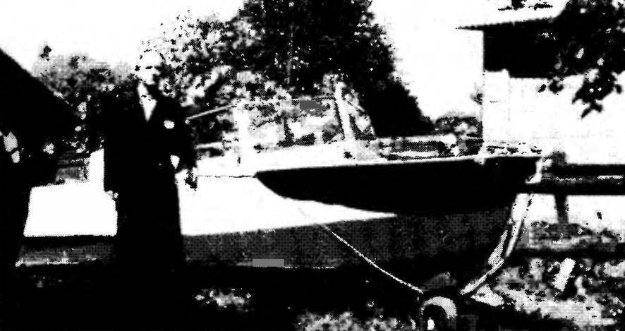
 Tourist boat-amphibian “AMFA” was built by Vitaly G. Lebedev 35 years ago. Over many years of operation it is, of course, has undergone several upgrades, but inherent in it original constructive ideas are outdated. AMFA is still pleasing to his Creator and his family, demonstrating on the water and on land of excellent quality. In the late 50-ies, when life after the war became easier and the children have grown up, I wanted to show them new places. We lived almost on the Bank of the canal Moscow — Volga, and water transport, as you know, the cheapest. So was born my idea to build a boat.