What lengths fishermen won’t go to for good luck.
Once my friend — an avid angler — complained that often the catch turns out meager simply because there’s no way to cast a bottom fishing rod to the spot where, presumably, the fish should be: either bushes are in the way, or there’s not enough strength.
That’s when the idea was born: to build a kind of mini-seiner — a small radio-controlled vessel the size of a model — to deliver fishing tackle to fishing spots, and at the same time “boilies” (bait in the form of balls).
Various radio-controlled ship models are available for sale. But, first of all, they’re not cheap (from thirty thousand rubles), and secondly, they still need to be modified to suit one’s own needs.
It was decided to make the hull from foam plastic, covering it on the outside with fiberglass on an epoxy binder — this is both cheaper and simpler than a shell hull with a frame.
As the power plant — to use a DC electric motor powered by a compact battery (an internal combustion engine wasn’t suitable for the vessel due to high noise.)
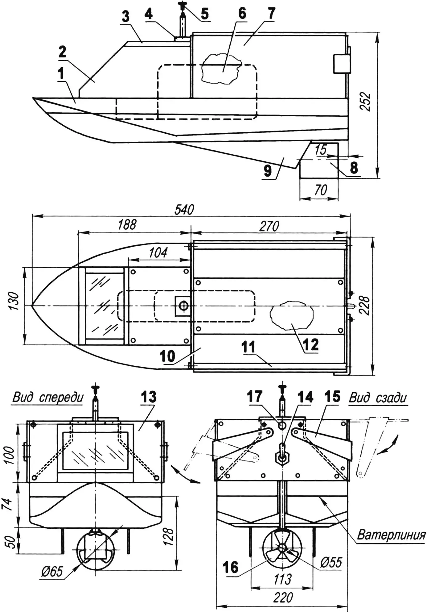
1 — hull (foam plastic); 2 — wheelhouse (foam plastic); 3 — wheelhouse cover (polyurethane foam s10); 4 — antenna bracket (stainless steel, sheet s1.5); 5 — telescopic antenna (purchased item);
6 — battery (purchased item); 7 — left side (right—mirror image, duralumin, sheet s1.5, 2 pcs.); 8 — propeller ring (brass, sheet s1); 9 — keel (fiberglass laminate, sheet s2, 2 pcs.); 10 — slide cover; 11 — side axle bushing (duralumin, square 6×6, 2 pcs.); 12 — platform with power unit and controls; 13 — frame: 14 — power switch (purchased item); 15 — side locking bracket (duralumin, sheet s1.5); 16 — propulsion-steering unit; 17 — signal light
Control to be carried out by radio.
The cheapest turned out to be Sanva proportional radio control equipment sold in “Pilotazh” stores. The command transmitter (command unit), receiver and two steering servos cost 4 thousand rubles. Another 1,300 rubles is added to this amount for a reversible speed controller from “Hitec” company. Of course, one could do without it, but then another steering servo would be needed to supply or disconnect power to the electric motor. But it also greatly limits the vessel’s capabilities. The reverse speed controller allows changing the speed of the craft (which is important when approaching the drop point), as well as giving reverse when maneuvering in reeds or algae.
I found sufficiently rigid foam plastic for the hull from discarded packaging from household appliances. Fiberglass and epoxy glue were purchased at a building materials store.

A 12 V electric motor with a gearbox — from a car power window motor of an imported car — I found in the garage among spare parts. The current it consumed was minimal — only 150 mA, which promised the possibility of operating the vessel without recharging the batteries for the entire fishing trip. The revolutions on the gearbox output shaft were low, and this prompted making the vessel with wheel paddle propellers — like old steamships, which gave it a distinctive appearance.
As for the mechanism for dropping rods and bait, the first thing that came to mind was to make a two-slope slide over the deck with slopes toward the sides, covering it with bulwarks. This solution allowed loading two rods onto the mini-seiner at once — one in each side compartment — and dropping them independently by opening the bulwark.
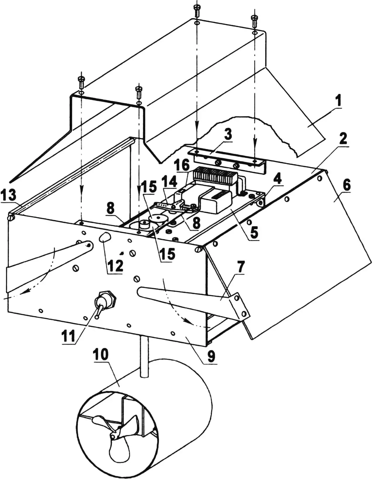
1 — slide cover; 2 — front wall; 3 — slide cover support bracket; 4 — angle bracket for platform mounting; 5 — platform; 6 — side; 7 — side opening-locking bracket; 8 — side unlocking rods; 9 — rear wall; 10 — propulsion-steering unit; 11 — toggle switch; 12 — signal light; 13 — side axle bushing; 14 — side opening servo rocker; 15 — reduction gear mechanism gears; 16 — command receiver
With this layout, the electric motor, steering servos (for controlling the swivel propeller column and opening the bulwarks), and batteries were placed in the hull’s hold. For visibility of the mini-seiner in the dark, blinking LEDs were installed on the bow and stern.
However, sea trials showed that the first attempt was a failure: the vessel moved sluggishly — it had great difficulty swimming against the current and was even carried away by wind and current. Moreover, water entered the hold through the wheel axles, which disabled the electric motor and nearly destroyed the steering servos. However, the mechanism for dropping rods and bait proved effective and worked flawlessly.
The conclusion was disappointing: a different layout of actuators, a high-speed power unit, and a different propulsion system were needed — it’s no wonder our ancestors long ago replaced paddle wheels with a propeller.
For the new mini-seiner, I purchased a “Spid-500” electric motor (costing 500 rubles), operating at 6 V, and for it — a lead-acid battery (costing 400 rubles). The battery dimensions are quite substantial: length x width x height — 150x150x100 mm, and the mass is about 1.5 kg. But its capacity is more than enough for the entire fishing trip.
The question of the vessel’s layout arose again. The classic scheme of transmitting torque from the electric motor through a gearbox and an inclined shaft line to the propeller would extend almost the entire length of the mini-seiner, and therefore fell away on its own — there was no room inside the hull for the large and heavy battery, especially since it needed to be placed as low as possible and in the middle of the vessel. But a solution was found — a rather rarely used scheme of transmitting rotation from the engine to the propeller through a vertical shaft and an angular gearbox (swivel propeller column or otherwise — propulsion-steering unit) was used. At the same time, all the main parts and mechanisms of the radio-controlled mini-seiner: the electric motor, steering servos and swivel propeller column are mounted on one platform — a fiberglass laminate strip 3 mm thick (a duralumin one 1.5 — 2 mm thick can also be used).
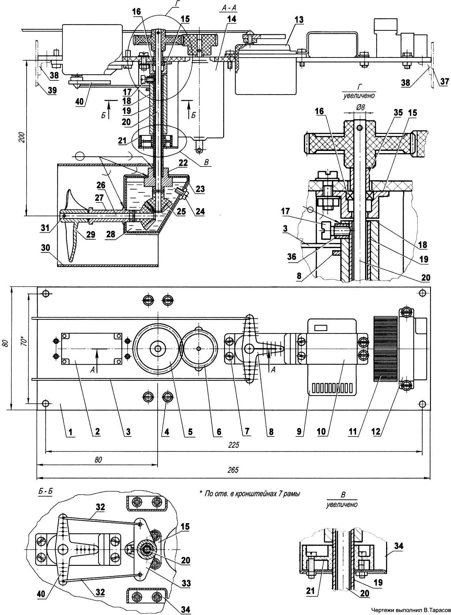
1 — platform (getinax plate s3); 2 — swivel propeller column steering servo — steering rudder (purchased item); 3 — side unlocking rod (OVS wire Ø1.0, 2 pcs.); 4 — unit bolt fastening (bolt M3, nut M3, washer, 8 sets); 5 — column shaft driven gear (capron z = 38, from copier cartridge); 6 — electric motor shaft driving helical gear (capron, z = 18, from copier cartridge); 7 — unit screw fastening (screw M3, 8 sets); 8 — side opening servo rocker (purchased item); 9 — receiver (purchased item); 10 — receiver mounting bracket and platform (duralumin, sheet s1); 11 — motor reversible speed controller (purchased item); 12 — controller mounting bracket to platform (duralumin, sheet s1); 13 — side opening servo (purchased item); 14 — electric motor (Spid 500, n = 9000 rpm, N = 100 W, purchased item); 15 — bearing housing (bronze); 16 — ball bearing 1000095; 17 — stop screw; 18 — lever swivel bushing (duralumin tube Ø10×1); 19 — column rod (brass tube Ø8×1); 20 — column shaft (steel, round 5); 21 — rod sliding bearing (capron); 22 — shaft sliding bearing (bronze); 23 — gearbox housing (brass, sheet s1); 24 — gearbox housing plug (screw M3 with capron washer); 25 — gearbox bevel gear (capron, from copier cartridge, 2 pcs.); 26 — propeller shaft (stainless steel, round 5); 27 — propeller shaft bushing (bronze); 28 — lubricant (litol); 29 — propeller (brass, sheet s1); 30 — ring (brass, sheet s1); 31 — pin (OVS wire, Ø2, 5 pcs.); 32 — column rotation servo rods (OVS wire Ø1, 2 pcs.); 33 — swivel column rocker (stainless steel, sheet s2); 34 — swivel column unit mounting bracket to platform (stainless steel, sheet s1); 35 — thrust bushing; 36 — threaded bushing; 37 — front wall; 38 — platform mounting angle bracket (2 pcs.); 39 — rear wall; 40 — column rotation servo rocker
Mounting seats for the steering servos and electric motor are cut out with a jigsaw with a metal blade or holes are drilled around the perimeter and then finished with a file. Fastening holes are made as usual — with the appropriate drill and tap.
Fastening to the platform of mechanism and device parts that don’t have their own mounting holes is done by means of brackets made from 1 mm thick duralumin sheet, with screws or M3 bolts.
When laying out parts and mechanisms on the platform, it’s necessary to precisely coordinate the distances between the centers of the electric motor and column shafts with the diameters of the driven and driving gears. At the same time, the column parts must not come into contact with the electric motor housing. I took the gears from an old printer and its cartridges. They’re capron, cylindrical, helical. The desired speed reduction at this stage is 2 — 3 times. But this isn’t critical. The motor is high-speed, and the speed can be reduced to zero using the radio control regulator.
The column consists of a vertical shaft installed in two bearings: upper — rolling and lower — sliding. Strictly speaking, it’s not the shaft itself that’s installed in the lower bearing, but a tubular rod fitted onto it. A spacer bushing with a rocker is also fitted onto the rod and fixed on it with a stop screw. This same screw regulates (limits) the column rotation angle. To fasten the column to the platform, a U-shaped (but inverted) bracket is used, on whose flange the lower sliding bearing is installed.
The lower end of the shaft passes through another sliding bearing (bronze). The rod is also inserted into it. But for the rod, the bearing serves as a tip, since the parts are soldered to each other. Subsequently, the angular gearbox housing is also soldered to this same tip, and the propeller ring to the rod.
It should be noted that the ring was installed later, after one of the fishing trips, during which algae got wound around the propeller and the mini-seiner was barely returned to shore. After installing the ring, this no longer happened, and moreover, the vessel’s controllability improved.
The angular gearbox consists of two bevel gears. In this case, they’re the same, capron, and also taken from an old printer (but different ones can be used, also using the angular gearbox as a reduction gear). One gear is mounted on the end of the vertical shaft, and the other — on the propeller shaft. A bronze bushing-bearing and the propeller itself are also fitted onto the propeller shaft. The gears are placed in a gearbox housing soldered from sheet brass, and the housing is filled with grease.
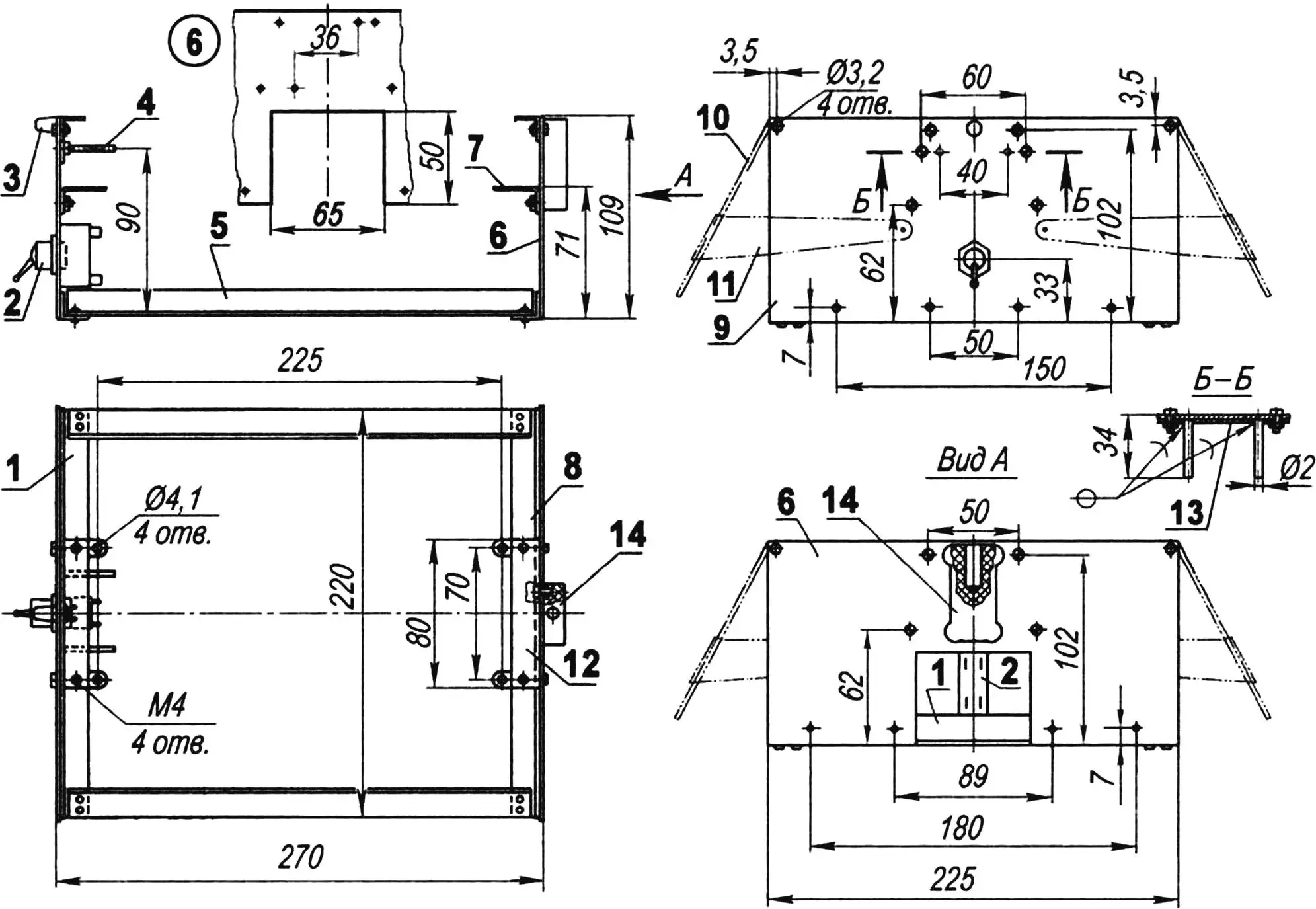
1 — rear cross member (duralumin angle 15×15); 2 — actuator power toggle switch (purchased item); 3 — signal light (LED); 4 — side opening-locking rod guide (MN95, tube Ø3×0.5, 2 pcs.); 5 — side member (duralumin angle 15×15, 2 pcs.); 6 — front wall (duralumin, sheet s1.5); 7 — platform mounting angle bracket (steel sheet s1, 4 pcs.); 8 — front cross member (duralumin angle 15×15); 9 — rear wall (duralumin, sheet s1.5); 10 — opening side (duralumin, sheet s1.5, 2 pcs.); 11 — side locking bracket (duralumin, sheet s1.5, 2 pcs.); 12 — slide cover bracket (duralumin, sheet s1.5, 2 pcs.); 13 — guide tube soldering plate (brass, sheet s1); 14 — antenna bracket (getinax)
The platform with actuators is mounted on the frame. The frame consists of two walls (front and rear), connected to each other by duralumin angles. Through holes in these angles, the frame is later fastened with self-tapping screws to the mini-seiner’s deck. A cutout is made in the front wall according to the battery thickness, and holes for the power switch and side opening-locking rods are made in the rear. In addition, various mounting holes and holes for signal lights — LEDs — are drilled in both walls, and two angle brackets are attached from the inside — the platform is mounted on them. The platform is covered from above with a cover with inclined “wing”-walls that serve as slopes of the two-slope slide.
Between the front and rear walls of the frame, swiveling lifting sides are mounted on axles. The sides can be raised either by the action of torsion coil springs installed on the axles (one end of each spring is fixed to the side, and the other — to the wall), or by the force of gravity of the dropped tackle.
Holding the sides in the closed position is done by the side opening servo rods through brackets attached to the sides and passed behind the rear wall. The sides open on command alternately, which allows dropping the load at different points in the water area.
The hull of the new “mini-seiner,” like the first one, is made of hard foam plastic and covered on top with fiberglass on an epoxy binder. It’s almost flat-bottomed, so for better course stability, two glued-in keels made of fiberglass are provided. Along the diametral plane approximately in the middle of the length almost to the bottom, a recess is made in the hull — a battery niche. The niche is one and a half times longer than the battery — for convenience of sliding the latter under the two-slope slide.
In the stern part of the hull, also along the diametral plane, a narrow but through slot is made for the column. A through slot, not a hole, is made only for convenience of mounting (or dismounting) the column (or the platform with all mechanisms assembled).

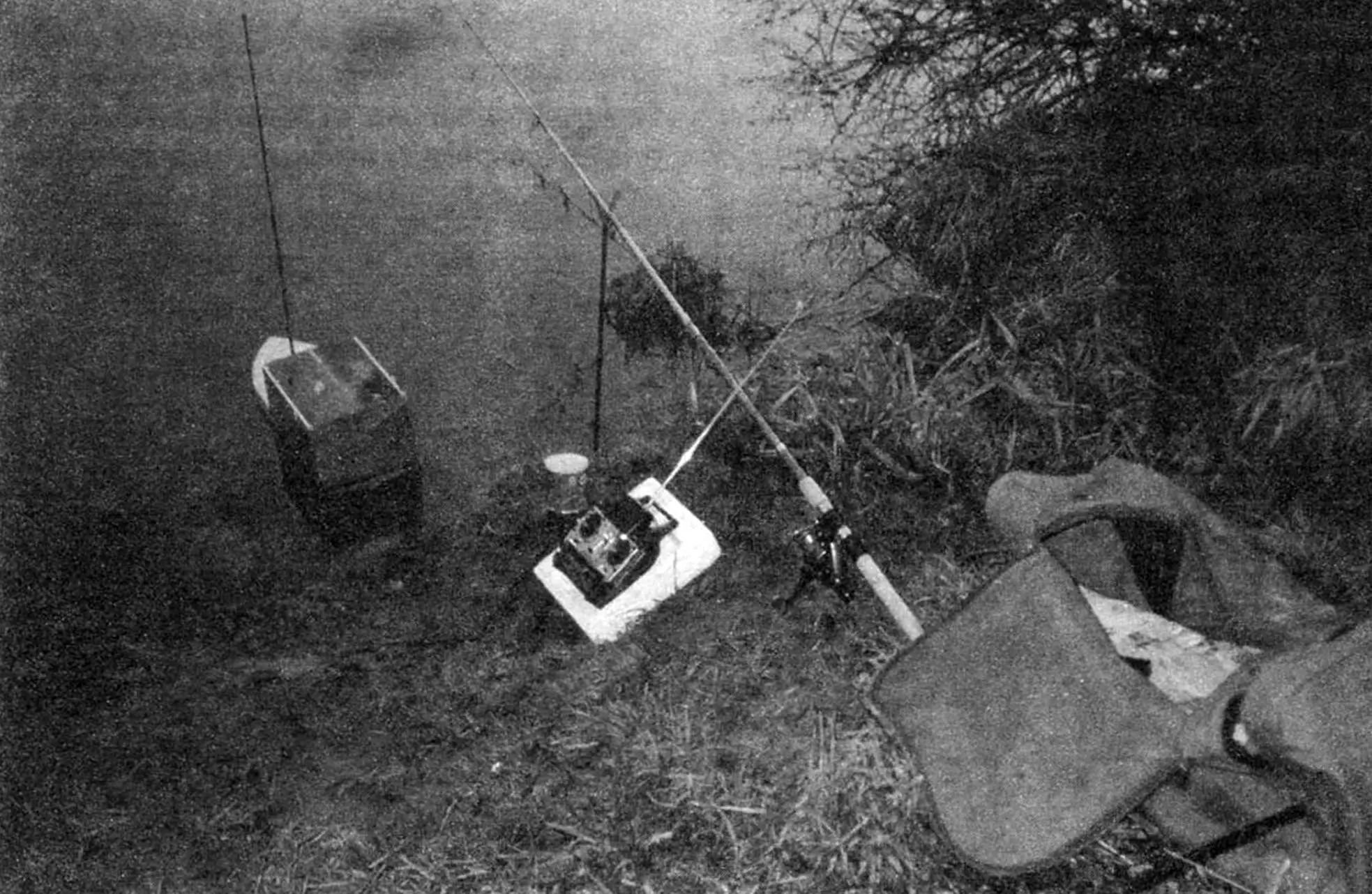
Now about the process of delivering rods and bait to fishing spots. Two rods with spinning reels released for free unwinding are installed in forked stakes on the shore about two meters apart. The “mini-seiner” is launched into the water between the rods, bow toward the target. “Boilies” or other bait are put on the rod hooks, and they, together with sinkers, are led from under the sides onto the slide slope (from each rod onto its own) — and the sides are closed. Then the required amount of bait is poured into the compartments, the radio control equipment is turned on, the onboard power toggle switch, and with a smooth press of the “forward” speed handle, the vessel is sent to the fishing spot.

The “mini-seiner” moves toward the target, the LED blinks, and the fishing line unwinds and trails behind. When the vessel approaches the desired point, its speed is slowed (to a stop) and a command is given to open the side. By the reaction of the line and reel (they also stop first, then unwind a bit again), it’s determined that a drop has occurred. It should be noted that no failures in this process have been observed so far. Then the “mini-seiner” is taken to another designated point and the tackle is dropped from the opposite side. After that, the vessel is directed back to shore.
On the very first trials, the “mini-seiner” exceeded our expectations and ensured successful fishing. At low atmospheric pressure, when fish weren’t biting for any of the nearby anglers, my friend and I caught a couple of two-kilogram carp. This was repeated more than once afterward.
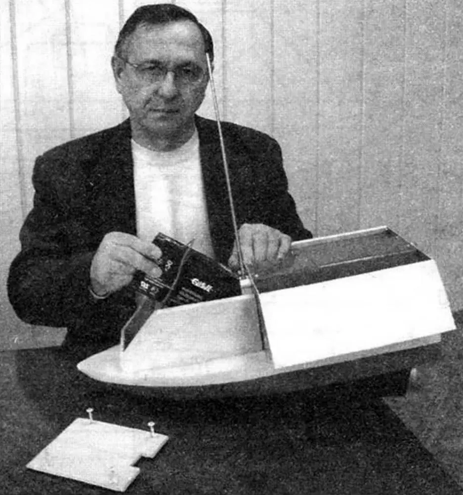
When performing tasks, the “mini-seiner” shows confident and fast speed even against the current, turns almost on a dime, and makes its way through reeds and algae.
The well-known rephrasing of the proverb: “Fish seek — where it’s deeper, and man — where the fish is” is exactly applicable to my “mini-seiner.”
To find such a place, I equipped the “mini-seiner” with an echo sounder. And now I open the sides not by intuition, but at that deep spot indicated by the device.
“Modelist-Konstruktor” No. 3’2008, V. IVANOV
Recommend to read
 HONDA CR-V 2006
The first multi-purpose four-wheel drive car with the name HONDA CR-V was released in 1995 and in 11 years of mass production sold in 160 countries with a circulation of 2.5 million... CLOWN OF WOOD, BUT AS A LIVING
Who in the circus like children? Of course, fun and funny clown. And a shaggy red wig, and bright baggy clothes with huge shoes, and tricks — all causes kids (and adults) happy laughter....
