Assembled MT-7 mainly from serial components and assemblies used equipment. All of them had, of course, to touch, to refurbish worn parts. And tried a radical alteration used serial components and assemblies not to. First, because in the case of any of them down to replace special difficulties not present. Secondly, he was convinced that alterations that were willing some fans – the designers, sometimes reducing the strength and reliability that is converted.
Take, for example, the input shaft of the gearbox from the car GAZ-51. Ispolzuya KP-51 design homemade mini-tractor, it is difficult to resist the temptation to shorten it. But, cutting the shaft, remove the most valuable slots. And now for fixing on the shaft of sprocket, gear, etc. you have to drill a hole for the bolt or to eat through the groove under the key. Unnecessary, in my opinion, work! In addition, the bolt — not slots: under heavy load it can simply be cut. And if homebrew wiser not yaracuy, save the shaft — no problems will arise. To the splines for worn clutch disc lining with remote to which you can attach any elementary item: flange, sprocket, etc. Additionally on the shaft is enough space to install additional devices for the selection of power for other components: water pump, mowers, circular saws…
Kinematic scheme of transmission:
1 — powertrain (engine from GAZ-69 with the primary transmission and clutch) 2 — driven (front) wheel (2 pieces, from the car “Volga”), 3 — extra transmission (from the GAZ-51 with box PTO and pump NSH), 4 — rear axle (from GAZ-51, short), 5 — lead (rear) wheel (2 pieces, tractor MTZ-52, on the wheels of the car GAZ-51), 6 — couplings flanged, open.
No alterations, no modifications, and the power unit, which is used as the practically trouble-free the engine from the GAZ-69 with a capacity of 55 HP, along with his transmission (having three forward speeds and one back) and a clutch. Torque with KP-69, which is in this case primary transmission is transmitted on the CP-51 directly, without “soft” connections through the flanges, fastened tightly with bolts. Similarly is also the connection of the CP-51 with the flange of the gimbal mounted on the master gear. Distortions here, of course, unacceptable. The exact longitudinal centre line set of series-connected nodes of the power transmission from the engine to the wheels of the rear axle fails to comply with, if the pre-assembled lead, as they say, on weight, having all on stands so that the nodes are in the same horizontal plane. Having the lack of beating, the bolts on the flanges (couplings) is rigidly fixed. Then transfer the design on the frame of the tractor, which is a isosceles trapezoid (height 2,400 mm, with the bases of 680 mm and 550 mm), made of a channel 120х50 mm for welding, wide ass out. Powertrain and chassis components are fixed in place, producing the final finishing of the kinematics (that never had any distortions). Then will test the entire structure. Let the engine some time to work in vain, why lift the rear wheel above the ground on trestles. Making sure that everything is in order, establish into place the remaining units and parts.
Actually, I do not advocate blindly copying anyone, even the most successful, developments. I am convinced that only rational to focus on selected as the prototype of the schema, using in its construction the details and features that the homebrew available. Therefore, talking about MT-7, deliberately omit the description and the specific dimensions of the brackets, struts and other details, features fastening certain parts. Each to the extent of their powers and abilities will decide arising in manufacture mini tractor questions, including about replacing, say, a second, additional gearbox from the car GAZ-51 with box PTO and pump NSH (which, let’s say you didn’t have on hand) on the same taken from other vehicles. Composing them into a coherent whole, it is necessary only not to forget: KP-51 the gear teeth are straight, small; others have the teeth, and the step of cutting, other. Hence, the necessary and corresponding electrical outlets.
The hydraulic pump is connected to benzo – and oil-resistant armoured standard hoses with malereproduction (of any type) and gidroboksom, a power cylinder for lifting mounted units, a dozer shovel and a mechanism for tipping the trailer.
The instrument panel — combined. Panel taken from the car KrAZ, instrumentation-pointers — from other cars with a 12-volt voltage.
On the right front fender MT-7 cut a rectangular hole to see the position of the wheel when monitoring progress during hilling.
Transforming front axle
“Highlight” in the design of the MT-7 is transforming the front axle. Using this technical solution allows to easily and quickly change the width of the ruts mini-tractor, which is becoming a really reliable mechanic assistant, not only when plowing a field, a garden, and performing other (usual for machines of this kind) operations; you can have a great treat aisle, to plant and hill potatoes, other root vegetables, taking into account the recommendations of the science and practice.
The basis of my proposed ideas — dvigaysya telescopically in each other structural elements. Thus, the dimensions of the design change significantly. For example, when hilling potatoes front wheels MT-7 moving away from each other, and the track width is not 1080 mm-1400 mm. For rows, cut at intervals of 700 mm, is the best option.
It is such a beneficial innovation is very simple. Instead of a single cross beam does two channels: 120х50 mm and 100×50 mm, bonded to each other with three bolts M12. The length of the channels respectively of 680 mm and 730 mm. With the expansion of the gauge bolts to Unscrew. The upper channel, sliding easily along the bottom, extends to the required distance (in this case 320 mm). Then both channel re-bolted.
Naturally, the extendable front axle must be increased and the length of the transverse thrust. The latter is composed of two pieces of steel angles that are attached to each other and bonded to each other by three M8 bolts. When changing ruts bolts to Unscrew. Extending transverse rod to the desired length, re-fasten the corners with screws.
Especially the performance of the other nodes and elements of the front axle clear of the illustrations. Let me just say that from the bottom, in the middle of the cross beam-channel 120х50 mm, welded bushing, which is a section of steel seamless pipe 30х5 mm (GOST 8734-75) and a length of 120 mm. The sleeve is inserted the axle in the form of M20 bolt passing through holes in the two transverse brackets (made from the area 50×50 mm), screwed to the frame of the mini-tractor symmetrically relative to the composite cross beam. The latter is teetering on the axis of the bolt, turning when driving on rough ground at the corner bounded on both sides by the lugs out of the corner of 45×45 mm. the Bracket for a more rigid fixation is additionally strengthened by two braces connected to the frame of the mini-tractor.
Steering wheel from UAZ — 452. My mechanical assistant it is located on the right side. Therefore, the fastening of the steering mechanism with the steering actuator on the MT-7 in itself does this. As for the lever, it is removed from the slots and then turning, pushed again, but in a vertical position.
Tie rod! Despite its unusual sliding, concisely set forth above construction to produce this important link is not so difficult. Especially for someone who is familiar with electric welding. It requires only welding lugs with ball fingers very elementary system of two sliding on each other parts of 30×30 mm, fastened with three bolts M8.
So, when cruising, for example, potato left front wheel slides out along with the channel 100×50 mm and 30×30 mm area sideways to 320 mm. the track of the front wheels becomes equal to 1400 mm. is Increased by a corresponding amount and the track of the rear axle. But not at the expense of transformation of the latter, and by setting in place the left rear wheel other: special, having a special design (see drawing).
It is easy to see that the ordinary is removable, used only when working with an extended track, different wheel weld-on hub. Located between “basic” and “ring” parts cut by torch drive, the last as it increases the length of the rear beam. And instead of the standard MT-7 gauge at the rear — 1000 mm — get (including the “car” method of fixing the wheels) 1400 mm.
Unlike the front wheels, with tyres 6,5-16 (from the car “Volga”), the rear wheels, the MT-7 — with tires of the tractor MTZ-52, the size of which (6,5-20) makes it easy to mount them on the wheels from the GAZ-51. Removable wheel here is no exception.
The tread pattern is “herringbone”. To increase the coupling weight of the mini-tractor can be recommended privertyvali removable cargo or filling chamber through the valve to approximately 2/4 of the volume of water (with the onset of low temperatures — 25% aqueous solution of calcium chloride, freezing at minus 32°C). With increasing soil moisture when the reciprocal relationship of parts is disturbed, increasing the thrust of the above technique is not ensured. In these cases it is advisable to reduce the tyre pressure.
Rear axle: long — shorten!
The rear axle of the car GAZ-51 appealing to many Amateur designers kitchenette appliances. Its reliability, availability finally. But the length…
Meanwhile, there is a long way even in “home” conditions to shorten the bridge. They are something I have used when making your MT-7. Since the “M-K”technology of shortening the rear axle of the car GAZ-51 was never published, and wanting to read it, it seems to abound, I would venture to share my experience.
First of all, of course, ZM clean, removing old oil and accumulated dirt. Then rear axle dismantled into separate parts. Unscrewing the appropriate nut, remove axle shafts (see Fig.), and raspolovinil Carter, to remove the differential.
On the stockings ZM a sharp chisel cut off the heads of rivets with a punch “utaplivayut” them inside, then gently with a hammer to knock the stockings from the casing. If necessary, sometimes have the seats warm up a blowtorch. And subsequently not suffer during Assembly, achieve precise alignment vzaimosoedinenii parts to each other — take care of timely application of stockings and differential case special marks (chisel, to the separation of component parts).
Stockings pritachivajut the diameter of the landing surface to cushion the springs, then left a cutter is shortened to 180 mm, right 235 mm from the differential. Cropped nylons are inserted back to their landing slot. And that they are thoroughly fasten, using the old holes in the differential where before there were embossed inside the rivet, drilled in stockings new. Existing (or specially made with a diameter of 0.1 mm large) rivets driven into those holes and flush welded by electric welding. After Assembly of the entire bridge is installed on a mini-tractor. To frame this GP is mounted on the M12 bolt passing through the holes, prudently done in the right places. Size A (see Fig.) is chosen such that the minimum track width on the rear axle was 1000 mm.
As for the axles, they serverlists side flanges strictly according to the center to a depth equal to the thickness of the flange. The drill diameter is slightly smaller than the diameter of the axle shaft. Next, the axle shaft face piercing holes according to the drill diameter to an appropriate length (see Fig., size B). For the right axle it will be 235mm, and to the left is 180 mm. Each is inserted into its flanges and with both sides thoroughly sealed (use electric, not a blowtorch!). The metal is not “released”, periodically cool the axle shaft flange with water. Then shorten the axle shaft by removing the cutter on a lathe.
Layout (lighting, marker and signal lights not shown):
1 — bonnet, 2 — radiator, 3 — fan, 4 — frame chassis, 5 — motor, 6 —vostokfilm, 7 — front axle, 8 — gearbox GAZ-69, 9 — panel, 10 — tool box, 11 — steering wheel column, 12 — a gear lever, 13 — arm include the hand brake, 14 — the lever of expedited transfer, 15 — clutch pedal 16 — accelerator 17 — gearbox from the car GAZ-51, 18 — the seat of a UAZ-452, 19 — lever valve, 20 — valve, 21 — the hydraulic power cylinder 22 — rear axle of the car GAZ-51, 23 — frame, 24 — hydropack, 25 — fuel tank 26 — tail, 27 — awning removable canvas.
Front axle (schematic representation):
1 — the wheel (from the car “Volga”, 2), 2 — node steering-left (relative to direction of travel), 3 — bolt M12 with nut (3 PCs.), 4 — beam transverse bottom (channel 120х50 mm), 5 — sleeve weld (120 mm section of pipe 30х5 mm), 6 — axis (bolt M20), 7 — M20 nut with washer, 8 — subframe-bracket (area 50×50 mm), 9 — transverse upper beam (channel 100×50 mm), 10 — hub Assembly (2 piece), 11 — node steering-right (relative to direction of travel), 12 — transverse traction (two telescopically dvigaysya each other of area 30×30 mm), 13 — frame welded (channel 100×50 mm), 14 — emphasis (cut corner 45×45 mm, length 120 mm, 2 pieces), 15 — bolt M8 with nut (3 PCs.).
Removable rear right wheel with the hub:
1 — the main part of disc wheels (GAZ-51), 2 — hub weld-on, 3 — ring part of the disc wheel (GAZ-51), 4 — wheel (front of the tractor MTZ-52).
Shortening the rear axle of the car GAZ-51:
1 — drive left wheel, 2 — light left, 3 — axis left, 4 — left stocking, 5 — rivet 6 — half Carter left, 7 — flange cardan, 8 — nut, 9 — half of Carter the right, 10 — stocking-right, 11 — axle shaft right, 12 — right spring, 13 — disc right wheel 14 on the axle flange.
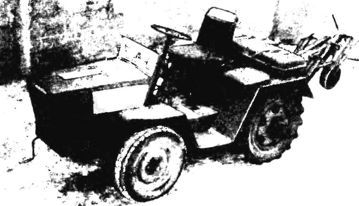
55 horsepower mini-tractor created by long-time author of “M-K” V. Chirkov from Moscow, Lotoshino. Among successful technical solutions found by the Amateur designer a compact arrangement of units and parts on the frame (see photo), the wheel, rotation of which is 180° is achieved by rapid changes of the track width at the rear axle, dvigaysya telescopically into each other transforming the structural elements of the front axle… And that is important to any economy — set mounted implements to successfully carry out the plowing-processing of even the heaviest soils.
About his mechanical assistant continues to tell the author of the design.
In the field and in the garden
To mini tractor stood idle, care must be taken to set a variety of mounted and trailed agricultural equipment. And especially for the quality of plowing, mechanized planting (for example, the same potatoes, other valuable crops), inter-row cultivation and harvesting of crops grown.
The location of the engine, units and parts on the frame of MT-7.
Scheme of soil treatment Hillers, together with the cultivator:
1-4 — Hillers with their sequence numbers, 5 — cultivator with chisel (for loosening flattened left wheel mini-tractors of the earth), 6 — wheel adjustable rubber-coated, 7 — frame Hillers (area 50×50 mm), 8 — node mounting to the subframe, mini-tractors, 9 — rear-wheel mini-tractors, 10 — soil profile when cutting ridges (Hillers 1-3 and 5 pubescent cultivator, mouldboard 4 raised), 11 soil profile at planting of potato tubers (first call; Hillers 1-2 and the cultivator 5 is lowered, the mouldboard is raised 4 1/2 height first, Hiller 3 is raised or removed), 12 — the soil profile in the following entry mini-tractor for planting potatoes (Hillers and cultivators similar to the previous paragraph), 13 — potato tubers (oriented with the shoots facing up).
The production version of the replacement wheel with welded on elongated hub.
Recommend for plowing to get one – and polutoratonny plows that can be done on their own — benefit in the “M-K” was published the appropriate drawings. Installed these tillage operation in the nests of a special frame: welded, steel channel 80 x 40 mm (see illustration), with special adjusting mechanism of rubber wheel, and an actuator of the hydraulic suspension. And since the MT-7 when plowing right wheels are in a furrow, the ploughs are defined with a deviation from vertical to the right to during the work they took a perpendicular position (compensation gives the slope of the hull mini-tractor). Respectively, and the toe of each plow must deploy 1-2 degrees, but the left. Then the resistance of the earth, “selecting” all gaps will turn this car around (again right), and both guns will be in the longitudinal plane of the mini-tractor.
Frame plows with tillage, etc. elements:
1 — wheel adjustable rubber (a decommissioned farm), 2 — horse plow, 3 — plow half or Dohany, 4 — adjusting mechanism 5 — frame plows welded (channel 80 x 40 mm), 6 — actuator hydraulic suspension, 7 — cylinder, 8 — frame mini-tractor welded, 9 — subframe (from a scrapped farm).
The production version of the frame of a plow tillage.
The cutting ridges are three Hillers (see appropriate illustration). When planting tubers, the Hillers are rearranged, respectively, in the other sockets, and at one time the mini-tractor planted into the prepared furrow tubers backfilled on both sides of the Hillers. Simultaneously, the third mouldboard, mounted to the left of the second of 350 mm and a little behind him, cuts a new furrow for planting tubers next patch. That is, in a single pass of MT-7 and performs the lowering of the previous and preparation of new furrows.
When the hilling of potatoes the front axle, as mentioned earlier, sliding from one side to gauge 1400 mm. the Rear left wheel is replaced with another special, with welded on elongated hub (see photo). And damage from treated potatoes does not occur.
Technical characteristics of mini tractor
Overall dimensions, mm: 2650х1100х1400
Base, mm: 1470
Track (adjustable) mm
front bridge: 1080-1400
for rear axle: 1000-1400
Weight (without trailers and mounted implements), kg: 500
Engine: GAZ-69
Engine power, HP : 55
The maximum transport speed, km/h: 40
Operating speed minimum, km/h: 1
Width when plowing, mm: 500
V. CHIRKOV, PN Lotoshino, Moscow region
Recommend to read Motorcycles. From the convenience to epinephrine People of the older generations still remember those days when motorcycle in Russia was a full-fledged means of transportation. In extreme shortage of cars and their very high cost, the... WINTER IS NOT TERRIBLE if you increase the intensity of the heating installation in free areas of heating pipes for additional plates-clamps made of heat conductive material (e.g., duralumin), as shown on the...