AND BECAME “ANT” MOWER

AND BECAME Work mower… It is in our electronic age is among the most difficult, exhausting. Especially if you have to mow the grass on small plots, slopes, forest glades and other awkward places where large machinery is not to turn around. Ease up here called nimble small-sized aggregates. For example, such as developed by young technicians from Chernivtsi oblast improvised mounted mower. Tests have shown that it is equipped scooter cargo “the Ant” was in the hay a truly indispensable mechanical assistant.

Why “Ant” taken over “base” for a homemade mounted mower? Yes, because it is unpretentious, reliable, and familiar to many villagers. The engine it has enough power and forced air cooling. And the presence of the reverse speed will guarantee a high mobility of the mechanical mower, allowing you to quickly mow the grass and grain crops, even in areas of width up to 1.2 m.
 
Linkage of the mower, on “Ant” does not cause any problems. Just drill four 8mm holes in the front panel and three 10-mm — in the frame of the scooter, to finalize the “basic” site and… to maintain it appropriately.
To install mower in the transport position it is only necessary to turn the transmission gear and moving the lever downward the lifting mechanism to raise the cutter bar. The effort of the operator is minimal — help compensating spring.
 
The lifting mechanism securely holds the mower during movement, so there is no need for special locking device. Well, to protect the cutter bar on him wearing cover-fuse (cut along the rubber hose).
 
For translation of the mower into the working position it is necessary to stop the scooter and remove the cover of the fuse. Moving the lever to control the lifting mechanism up and lower the cutting unit, and the other lever to turn on the first, the slowest transmission. Then, slowly touching the scooters with space to add on the “gas” until a stable engine speed. The mower is ready to work. Due to the compensating spring pressure support boots on the ground will be minimal.
 
TECHNICAL DANNIE MOWER.
 
Location of major components and parts of the mower on a scooter
 
The location of major components and parts of the mower on a scooter:
1 — scooter “Ant”, 2 — “basic” part of the frame of the scooter, ^ 3 —frame gearbox mowers, 4 — gear, 5 —gear shift lever of the gearbox, 6 — crank 7 — shaft output gearbox, 8 — rod, 9 — hinge joint, 10 — bracket “ears” of the mounting of the compensating spring 11 spring cover (2 PCs), 12 — spar-right, 13 — left side rail, 14 — Koro. myslo, 15 — cutting machine, 16 cover, fuse, 17—bracket knife, 18 — thrust Adjuster (2 PCs), 19 — clip coupling (2 PCs), 20 — main unit rotary mechanism.


Docking station
 
Docking station:
1 — hub sprocket of the input shaft (from the gearbox of a bike “Vyatka”), 2 — cut roller chain, 3 — asterisk’ for Cycling (2 PCs), 4 — sleeve-ground (pipe 37×4 mm), 5 —sprocket output shaft of the engine.


So a reducer to fit the mower with a power unit
 
So gear mower struitsya with Silom unit.
 
The power unit of the scooter, converted into gear mower.
 
The power unit of the scooter, converted into the gearbox of the mower:
1 — input shaft with gear and mechanism of their switching, 2 — intermediate shaft with gear unit, 3 — sprocket from moped (t= 14), 4 — Bush roller chain (cosmetic), 5 — output shaft (Steel 45), 6 — the sprocket from a moped (g=13), 7— bearing 180206 (2 PCs), 8— dividing bushing of the output shaft of seamless steel pipe 30×1,5 mm (3 PCs. with a length of, respectively, 15, 20 and 42 mm), 9 —groove parallel key 8x7x20 mm.


Frame reducer
 
Frame reducer:
1 — leg clamp (4 mm thick, St3, 2), 2— clamp (steel water-gas supply pipe 60×5 mm), 3,4 — large and small cheeks (thickness 4 mm St3), 5 — base section of the frame of the scooter, 6 — cantilever plate (5 mm thick, St3).


Connecting rod
Rod:
1 — rod (steel pipe 38x30x2 mm rectangular cross section), 2 —adjustment bushing (steel seamless pipe 21×5 mm).


Hinge joint
 
Hinge joint:
1 —rubber bushing (2 PCs), 2 — grease (grease), 3 — the aluminum bushing (2 PCs), 4 — o-ring (2 PCs), 5 — axis (seamless steel tube 17×3. 5 mm), 6— the basic plot of the frame of the scooter, 7 — washer (2 PCs), 8 — spar mowers, 9 — M12(2pcs.).


Side member left (a) and right (b)
Side member left (a) and right (b):
1 — mount plate to the hinge node (St3), 2 — the case of the spar (steel pipe 34×2 mm square section), 3 — mounting bracket compensating spring (steel angle 25×25 mm), 4 — finger lifting mechanism (ST5), 5 — “Shoe” (strip section 25×3,5 mm St3), 6 — a plate of fastening of the cutting device (St3), 7 — the axis of swing of the rocker (ST5).


Rocker
Rocker:
1 —taper bushing (2 PCs., ST5), 2 axle (ST5), 3 — base , (St3)


The main swivel
The main rotary site:
1 — coil spring spacers, 2 — minimalesk, 3 — flange (2 PCs., STD), 4 — Bush-Foundation (steel водогазопроводнаятруба33,5×3,5 mm), 5—lever (ST5), 6— shaft rotary unit (steel vodova Zapovednaya pipe 25,4×4 mm), 7— the lever of the lifting (2 PCs., STD).


Linkage Assembly
 
Linkage Assembly:
1 — left side rail, 2 — thrust Adjuster (2 PCs., ST5) with nut M16, 3 — clip coupling pieces (2, St3), 4 — bracket (2 pieces, strip section 50×4 mm St3), 5 — main swivel, 6 — spring offset (2 piece), 7 — bracket “ears” (St3), 8 — reducer, 9 — spar-right, 10 — rocker 11 — bracket knife (St3), a 12 — rod.


A few words about the mode “stop”. To lawn mower stopped working, need to stop the scooter (this will cease to move the crank) and switch the gear lever to the neutral position. All done.
 
As for the required for the manufacture of mower components, parts, materials, and then, as they say, win-win. Because almost everything here is junk or used. Starting from the gearbox (borrowed from the exhaust of the power unit VP-150, which once stood on old scooter “Vyatka”), the cutting unit and the crank mechanism (the decommissioned combine harvester “Niva”) and ending segments of steel pipes and other scrap metal.
 
The kinematics of the mower is so simple (and so reliable) that draw it in a separate scheme is hardly appropriate. Moreover, there are sketches and photos of the main units, assemblies and parts.
 
When the mower torque is, of course, from the power unit of the scooter through a special docking port is attached to the input shaft of the gearbox.
 
As a reducer, as already noted, used the power unit VP-150 from scooter “Vyatka”. On the way he installed the crank mechanism. And the latter via rocker arm, pivot bearing, and other elements kinematically connected with a movable knife. But the other (cutting) mechanism.
That’s all.
 
Fabrication and debugging of key components and parts of lawn mower such that it is necessary to tell apart.
 
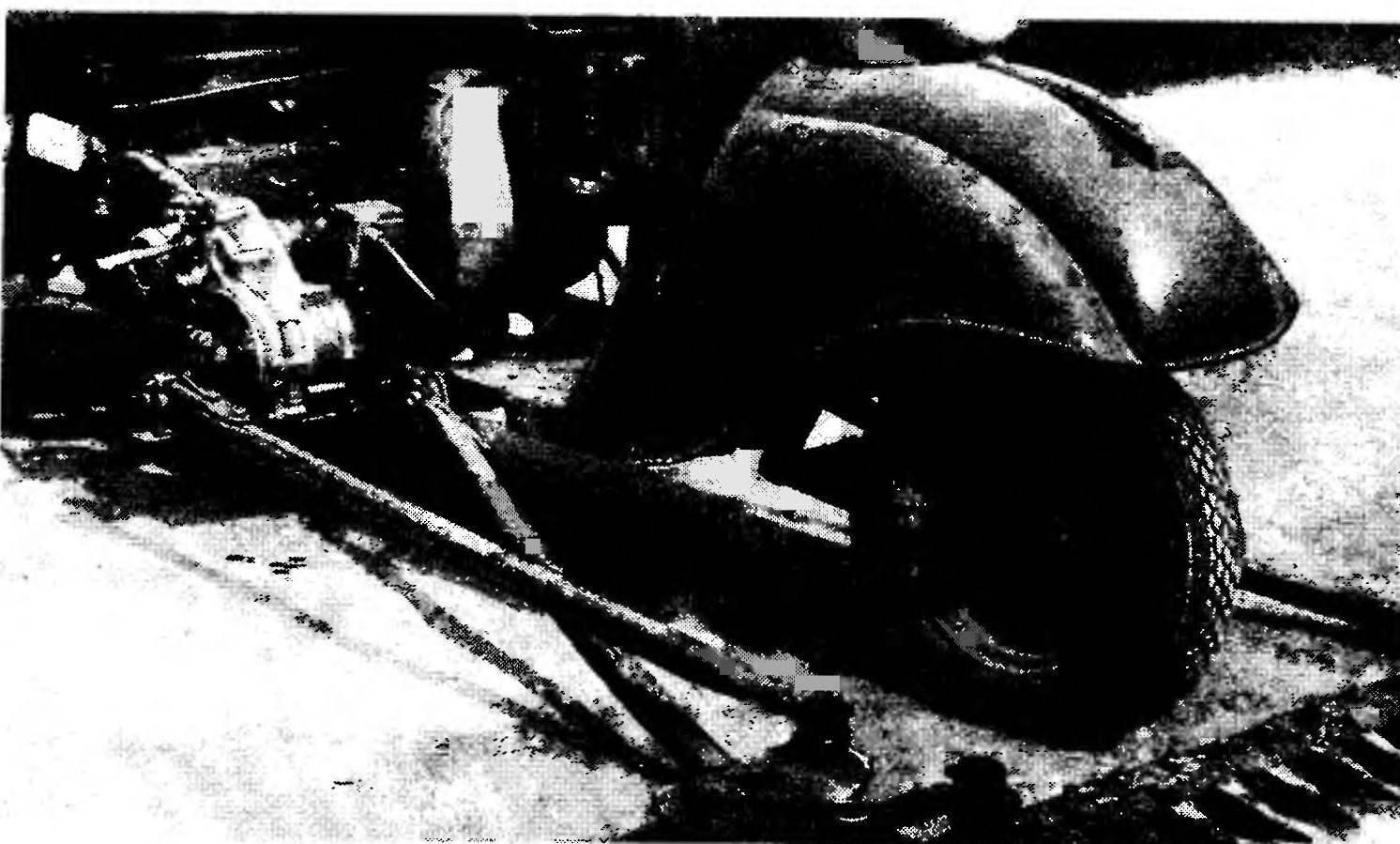
First of all, the docking station. It is based on a section of pipe. On the one hand welded it to the motor sprocket (g=15) of the motorcycle “Minsk”, on the other — the crown of the Cycling stars (g=18).
 
The latter, located close to similar (and related together cut roller chain), transmits torque to the input shaft of the gearbox. The crown of this sprocket-double welded to machined to a diameter of 37 mm the hub, once belonging to the gear with the slot-howl fit on the considered shaft (in those days, when the gearbox was part of the powertrain of the motor scooter “Vyatka”).
 
It is impossible here not to mention that when you install the intermediate compounds in place of the first fixed motor sprocket (g=15). And only after that cut the chain connecting two of the ring gear of the Cycling stars-twins. For the manufacture of gear mowers used compact power unit VP-150 from scooter “Vyatka”. In one housing there are three-speed gearbox, the mechanism of its switching and crankshaft.
 
This unit was completely disassembled: removed the intermediate gear unit, raslaan a damping mechanism is removed and helical crown. The hub of the intermediate block machined to 44 mm diameter, and welded the sprocket from the moped (g=14).
 
The old crankshaft bearings removed and installed new — 180206 (radial, single-row sealed). The inner diameter of these bearings is the crankshaft machined a new shaft — output. With one side milled a keyway, with the other welded the sprocket from the moped (g=13). Then the unit was assembled, now as gear — with a new output shaft and Bush roller chain connecting the sprockets.
 
To the “Ant” reducer is attached to its frame, which consists of two steel plates (large and small cheeks) with holes for coupling with the frame of the scooter. On top of both cheeks welded to the attachment housing reducer tube clamp, bottom (only to the big cheek) — other node — cantilever plate.
 
The left side rail of the mower from the square tube. To the ends it is welded on the plate: one for connection with the pivot node, the other (with two holes) for mounting the cutting unit. On top of the spar is cut a steel square with twelve holes for adjusting the tension of the compensating spring and the finger joints with a thrust of the lifting mechanism; a bottom “Shoe”, which is copied terrain
 
FIELD.
 
The right side rail like the left, only in the plate for suspending the cutting unit done another hole and welded in the axis of swing of the rocker arm. The bottom of the axle screwed in lubricating oiler.
 
A hinge Assembly is mounted in the tubular part of the frame of the scooter. The rubber bushing in it to reduce vibration. Pair of “rubber Bush — axis” smeared with grease.
 
Used factory crank, harvester combine “Niva”. However, with a small mod — with it removed the drive sprocket. Mounted on the splined end of the output shaft of the reducer crank connecting rod connected to the cutting apparatus.
 
The connecting rod is made of thin-walled tubes of rectangular cross section. Front of it is welded to the threaded sleeve, which is used to adjust operation of the cutting apparatus; on the other hand the drilled holes for connection to the crank.
 
The rocker is built like the similar parts of harvester combine “Niva”. For mounting of ball bearings here welded two sleeves with conical holes and the trunnion axis of the swing. As for the ball joints, they are taken from the sidecar of SZA.
 
With a yoke pivotally connected to the bracket knife cutting machine. It is made by welding segments of steel strips and riveted to the back of the knife.
 
As already mentioned, the cutter bar of the mower used from a harvester combine “Niva”. The back side of the carrier gon, however, had to be reduced to 20 mm. And the regular bolts finger to replace a similar, but flat-head (mounted mower KS-2,1). This upgrade gave the maximum effect, the holes in the fingers had been the first to razzenkovku and then turn a file into a square to prevent rotation of the bolt heads. The result has been to reduce the height of cut when mowing to 35 mm.
 
The lifting mechanism. Design it is possible to tell, typical for small-sized agricultural machinery. Based here arm-swivel system with adjusting rods, tension brackets, compensating springs, and stub connections. In our case the system is installed in its place using bolted connections in the middle part of the front fender “Ant”. Return the bracket with the “ears” on the base of the frame of the scooter.
 
Finally, the main swivel site. It is, in fact, rests on two coaxially (coaxially one inside the other) located pipes. The outer is a base, and the inner — shaft welded to it a lifting and control levers. Lift arms finger joints are connected with the adjusting rods. The latter are eliminated and biases (if they occur) of the cutting apparatus.
 
V. Nikityuk
head of club “Young technician”, Kelmentsi, Chernivtsi region.

Recommend to read

  • IN A MODERN STYLEIN A MODERN STYLE
    Round tables are in fashion: buying new furniture, they are often sent to a landfill. However, this is hardly justified. To verify this, just look at the figure — four boards plus round...
  • THE WIRE — THETHE WIRE — THE
    To harden a steel part in a domestic environment, it must first be heated, as, for example, on a gas burner. However, the question arises: what is its holding? Pliers or forceps are not...