 Sharp and correctly sharpened tool was always a sign of the professionalism of its owner. However, it is important skill to master to bring their production tools to a working state. But the quality of the sharpening tool is a simple touchstone or elektrotochilo is not only long but also difficult. They are replaced by more productive equipment and machines of industrial or self-production.
An example of this is a universal grinding machine developed by a regular contributor to our magazine, Vladimir Ivanovich Petrov, an Amateur designer from Krasnoyarsk region.
In this taiga region, where a significant portion of the population professionally or for domestic needs busy with woodworking and where almost every third house has a chainsaw, the life shows that at least in lespromhoze workshop, but such or similar grinding machine just need.
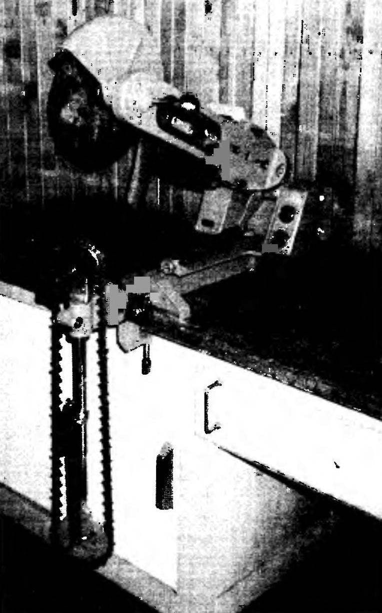
Universal grinding machine, or, in short, PSM is designed for a variety of applications in metal processing. It can, of course, and simple elektrotochilo. But has many other possibilities. It cannot, for example, not only conventional grinding plumbing and carpentry tools, including drill bits, cutters on wood and metal, but recovery under strictly defined angles of the teeth of the saw chains brands ПЦУ2-9.3, ptsu-of 10.26 and PCP-15, used in petrol and electric saws. Good machine also for cutting metals and simple diamond abrasive wheels, wood processing (cutting, sawing, cutting tenons, etc.).

Fig. 1. Universal grinding machine (a— side view; b — back view, without frame and attachment for chain sharpening):
1 — attachment for sharpening saw chains; 2 — clamp hook remover saw chains; 3 — rotary console console; 4 — handle of the crank the saw chain in the fixture; 5 — grinding wheel; 6 — protective cover; 7 — a lamp of local illumination; 8—the case of the pendulum; 9 — motor; 10 — switch box; 11 — handle feed of the abrasive wheel; 12 — an intermediate flange; 13 — V belt (type a, 1,850); 14 — power arm with a balancing mechanism of the pendulum; 15 — the mechanism of a tension of a belt; 16-electrical power outlet; 17 — detail of the locking mechanism of the pendulum (and, in the inoperative position, b in operating position); 18 — indicator lamp; 19 — housing electric fuse; 20 — switch to reverse the motor 21, the switch light bulb local lighting; 22— button “start”; 23 — “stop” button; 24 — rubber Bush; 25 — base; 26 — electrical cord with plug; 27 — clamp attaching machine; 28 — control panel; 29 — the hinge of the pendulum; 30 — combined bracket; 31 — reflector light bulb local lighting; a 32— protective rubber apron; 33 — power bracket; 34 — the mechanism for adjusting the position of the pendulum in the off position

Fig. 2. Machine dimensions

These operations do not exhaust the list of runs on the universal machine works.
Such a wide range of opportunities achieved through design features of the machine and the attached devices. On top of that CCS has a small size, allowing you to use it even in cramped workshops, and can be easily disassembled into three parts.
The undoubted additional advantages of the machine need to also include the fact that maintenance of the unit is minimal. In practice it is mainly to control the tension of V-belt Yes infrequent application of thick grease (grease) on the vertical axis of rotation of the power bracket.
Before turning to the constructive characteristics of the machine, I would like to note the following. I think the reader will be easier to understand the device as a whole, considering it to start at the individual components of the machine. Therefore, they are first presented on the drawings in the form of scattered details is a kind of directory nodes, and then they will be considered in detail in the collection.
PSM (Fig.1) consists of a pendulum mounted with a motor, of the hinge of the pendulum, the power box bracket, control panel, which is arranged almost all electrical equipment of the machine, and stand, firmly fixed to a workbench clamp (Fig.5). Such a large number of parts has necessitated a corresponding approach to their layout which would ensure not only reliable performance of the design, but would allow to achieve its compactness and ease of performing various operations.
So, for example, the longitudinal axis of the pendulum, when viewed from the side of the clamp, shifted to the right relative to the longitudinal axis of the frame. This decision helped to more evenly distribute the weight of the structure to increase its stability and reduce the size.
A similar approach was chosen and the decision of such tasks as installation angle vertical “guidance” of the pendulum: it is also selected using a simple mechanism, consisting of a round knurled nut and adjusting screw. They are installed on the rear wall of the power bracket. Due to the small step threaded offset they can be used for accurate feed of the abrasive wheel for sharpening of joiner’s and metalwork tools.
In the inoperative position the pendulum is held in the air by members of another simple device — the locking mechanism (Fig.1). It consists of a spring loaded hook located at the hinge of the pendulum, and brackets mounted on the power holder; it includes and engages the hook at the time of suspension of the pendulum.
Welded box housing of the pendulum (Fig.6) has sufficient rigidity, which allowed to install the motor directly on it without additional brackets. At the same time, the housing serves as a casing of the belt transmission.


Fig. 6. Pendulum:
1 — ball knob; 2 — lever; 3 — right bearing housing; 4,8,22,27 — bearings 6202; 5 — driven pulley; 6 — working shaft; 7 — the case of the pendulum (steel, sheet s8, the sheet s4); 9 — left bearing housing; 10 — hub; 11—clamping flange; 12 — washer; 13 — nut М14х1,5; 14 — a protective cover; 15 — a protective rubber apron; 16 — compression spring; 17 — pin; 18 — motor; 19 — screw M5 split washer; 20—combined bracket; 21 —bracket junction box; 23 — screw M6; 24 — torsion spring; 25 — the hook of the locking mechanism of the pendulum; 26 — hinge of the pendulum; 28 — nut M8 with split and flat washers (3 comp.); 29 — screw M8 flat washer; 30— spacer (3). 31,32 the bolt, nut and the M5 lock nut of the mechanism of a tension of a belt; 33 — prismatic keys; 34 — screw M5 split washer (6 comp.); 35 — grinding wheel; 36 — rivet; 37,38 — plug and socket electrical connector; 39 — driving wheel; 40 — V-belt; 41 — spacer washer
In the case of its sides cut window dual roles; they reduce weight and in addition allow you to visually inspect the V-belt tension. Further cut and the lower window; through him spontaneously removed a small foreign body, accidentally fell into the enclosure of the mechanism.
Back to the body welded flange with two arc grooves for the screws that it is secured to the flange of the hinge of the pendulum. These screws set the angle of lateral tilt of the housing; smoothly turning your body within the length of the arc grooves or step — by permuting the screws in the other tapped holes of the flange of the hinge of the pendulum. Throughout the circumference of the latter caused the limb with divisions of 1.5° for counting the value of the required angle.
The hinge of the pendulum (Fig.4 and 6) is a mixed node. It is made in the form of a sleeve with two bearings inside and a lever gauge, flange and gussets welded on the outside. In the vertical plane it rotates on the axis, which is a shaped bolt with two landing tails for bearings. The threaded end of the shaft is screwed into the right hole of the power bracket and the fixed nut (Fig.5).
Main technical specifications of universal grinding machine
Overall dimensions, mm:
length………………………………………………………………………………..654
width……………………………………………………………………………..300
height……………………………………………………………………………..1115
Weight without accessories, kg…………………………………………………21
Motor type………………………………………………AVE-0.71-4C
Rated motor power, W……………………….180
The number of revolutions, Rev/min……………………………………………………….1350
The maximum power consumed by the machine, W…………….250
Rated voltage…………………………………………………220
Power supply frequency, Hz……………………………………………………..50
The mode of operation of the machine………………………………………long
Transmission type………………………………………………………………belt
Gear ratio…………………………………………………………………1
The amount of work (sharpening, cutting, sawing, etc.) performed on the machine:
main………………………………………………………………………………5
total……………………………………………………………………………Yes 10
The maximum size of the used abrasive wheel, mm:
diameter…………………………………………………………………………….230
thickness……………………………………………………………………………..25
V. PETROV, S. fish, Krasnoyarsk Krai
(To be continued)


