In any close-fitting balsa between the panels in place the rear edge of the padded tape of thin glass with a width of 40 mm, the reinforcing and supporting knife-like part.
The wing spar, rather, its shelves, variable cross-section — from 3X12 mm in the wing root to 3X5 mm at the end of the console. They are made of high quality grained pine. In the Central part between the shelves glued into the box under the metal tongues of the hinge wing on the fuselage, a significant portion of the spar sewn on both sides with plywood with a thickness of 1 mm. the Balsa wall is installed after assembling the frame of the wing. The balsa ribs with a thickness of 1.8 mm and sort them in a way that is closer to the fuselage was located made of a dense wood, light, leave the wing tips.
In the root part of the consoles glued FRP pipes, canisters, if necessary (mainly for exercise, “speed”) to fit the ballast rod casting. Actuator Aileron — torsion type. Rotating pull can be made from thin-walled dural tube Ø 5 X 0.5 or wire grade optical fiber Ø 3 mm. At the end it carries a quick connect coupler with d-pad included in the second node of the center section of the fuselage. This decision proved to be the most reliable. In all situations, when there was a reset consoles, the drive system of the ailerons did not require subsequent repair or adjustment. After putting on the wing on the languages of the sample it is additionally fixed by tightening the console with a rubber ring. Fittings in the root rib glue small but strong enough wire hooks.
Wing tip in the form of a flat bevel, increasing the effective angle of transverse V. It is much easier to manufacture than rounded, it allows you to leave the building, the angle V is very small, which has a positive effect in the flight model “on the back”.
Equally important for success and aerodynamic solution to the model as a whole. The minimum cross section of the fuselage, the absence of any cracks, ledges, the slightest surface defects, high quality exterior, correct execution of the fairings and wing joints of the control surfaces with the planes and tail, carefully podobrannye combination of handling and stability — only this will allow you to take full advantage of the profiles of Applera.
That’s why with no less attention should be given to the performance of other elements of the airframe. The nose part is laminated of fiberglass of (0.05, 0.25 and 0.05 mm) in the negative matrix. Butt joint passes through the vertical plane of symmetry of the fuselage, the canopy is cut from the finished bow with a thin blade from a jigsaw. The loop holes in the fuselage and a flashlight and fringes along the line of the joint with a frame made of plywood 3 mm thick Before assembling the fiberglass halves to them adjusted the frames and foam (material PVC) unit. In the last slotted recesses for stacking batteries, receiver and servos radio system that not only eliminates the need to install many shelves and brackets, to to that protects the equipment in critical situations.
Pay special attention to the set of nodes that specifies the position of the wing relative to the fuselage. The plane of the lower part of the contour of the ribs substantially parallel to the construction centerline, which provides the angle of attack of about 2°.
The tail section is fiberglass conical tube formed by winding three layers of fabric thickness of 0.05 mm on a supporting metal frame. With the nose she joined tubular fiberglass insert.
The design of the all-moving stabilizer:
1 — the leading edge (balsa 6 X 8mm), 2 — boss front pin (beech), 3 — lining (0.8 mm balsa S), 4, 7 — rib (balsa S 1 mm), 5 —tube hitch stabilizer Ø 4 X 0.2 mm, 6 — spar (balsa’s 3 mm), 8 — trailing edge (balsa 3 X 12 mm).
A TABLE OF THE COORDINATES OF THE PROFILE
It should be noted that the fuselages, produced by the new technique of two separate parts, well established n in operation.
The design of the tail is clear from the drawing. The only thing I would like to advise save every gram. Easy the tail of the device is the key to its good controllability and stability.
Ready-made model elements have the following mass: wing (both consoles) — 680 g fuselage keel without instruments — 240 g, the stabilizer with pins — 40 For the equipment there are more than 600 g, it means that you can use and improvised.
During debugging control system, verify that all the controls are easy to move, whether there is no backlash in the joints of tie rods with the control horns and the coupling of the drive of the ailerons. All-moving stabilizer should deviate by 10° in both directions, rudder — 20-25°. Last mated with the ailerons deflecting up and down at different angles (+24°, -15°), which is achieved by forward tilt of the pylon, located in the center section.
Stabilizer exhibited with zero angle of attack relative to the axis of the model, only when performing the first exercise, he lowered the trim tabs at — 1°. Folding canopy-brake opens at 35°, and large angles cause the appearance of the pitching moment. But at these values, the inhibition model is very effective.
In conclusion, I would like to acquaint modelers with interesting methods of exercise “speed” As shown by calculations and confirmed in practice, spectacular dive Vered entrance on the measuring distance for acceleration of a glider, flying at a low altitude on the horizon with the subsequent attack and combat u-turn to reverse course contain a lot of elements on which a significant portion of the potential energy accumulated at the start, lost is meaningless. This is especially true of reversal: perform it related to the growth of aerodynamic resistance of the model.
The design of the fuselage:
1 — foam block, 2 — batteries, 3 — single tray servos, 4 — servos, 5 — folding lantern-brake, 6 — node sample of the lantern, 7 — receiver control system, 8 — dural box mounting of languages, 9 — power frame, 10 — hole wiring rubber ring, 11 — fuselage drive unit Aileron with the control horns, 12 — additional frame, 13 — drive cables of the tail controls in budanovoy shell, 14 — front edge of the keel (balsa), 15 — strengthening the edges 16 — wall power box keel (plywood S 0,6 mm) 17 — the horn of the rudder 18 — mounting window 19 g— bulkhead mounting budanovoy sheath cables, 20 — tail boom of the fuselage, 21 insert, 22 — the nose of the fuselage vyklicky, 23 ~ towing hook 24 — beech boss fixing Board, 25 — language linkage console (D16T), 26 — wing (balsa), a 27 — rib of the center section (plywood B 2 mm), 28 — sheathing of the keel (balsa’s 1.5 mm), 29, 31 — plywood lining, 30 — tube-axle (stainless steel Ø 4.5 X 0.5, sealed in the keel), 32 — rocking allopourinola stabilizer (D16T 2 mm), 33 — unit junction cable with a rocking chair, 34 — rear pin hitch stabilizer (wire OVS Ø 3.5 mm), 35 — front pin hitch stabilizer (wire OVS Ø 2 mm) 36 — the trailing edge of the keel (balsa s 4 mm), 37 — the leading edge of the rudder (balsa), 38 — rib (balsa S 1 mm), 39 is the trailing edge of the rudder (balsa 3 X 12 mm).
Rational not to seek to gain the maximum height. Loaded ballast model still not released in full Leer. In moderate height the last seconds of the winch should not be used on sluggish rise, and the additional acceleration of the glider. He seems to be fired directly at a distance, having not only greater speed but also enough headroom height. It follows a steep decline (acceleration), during the forward passage of the measuring base running stretched a half-roll. By the end of the first flight model is in position “on back”. Some do not bring it to the end of the base, abruptly give up, no elevators. The apparatus through a downward half-loop (still overclocking!), going a little beyond the mark, goes into a normal flight back, again with the decline and dispersal. As you can see, senseless plots of braking on this path, no!
THE BASIC DATA MODEL
Scale, mm . . ………….2400
Wing area, DMG…..52,3
The surface of the stabilizer, dm2 . . 6,0
Takeoff weight, g……1600
Ballast weight, g ….. . 1000
Load unit, GS/dm2 ……… 30,6-49,7
A. DMITRIEV, master of sports of the USSR
Recommend to read WEATHER ICON It is known that under the influence of moisture flat sheets of paper or cardboard several diverging and begin to warp. This quality can be used for production at home is simple device,... WITH A PROPELLER IN THE WATER… The propeller, or, as at the dawn of aviation, the propeller is experiencing a rebirth. The reason is the emergence of daltelecom and motor paragliders with very advanced rotor settings.... 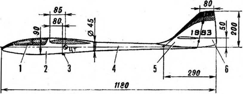
 None of the types of modeling to the apparatus is not presented at the same time so many conflicting claims as to RC jumper gliders. Imagine that you need to design a machine that combines the properties of high-speed models, gliders-paritala and apparatus created specifically for ustanovlena of records range.