One of the main challenges was finding ways to increase in cruising and maximum flight speed while maintaining constant specific load on the wing. After all, modern trikes landing mechanization have not (and implementation of it to date is problematic). Therefore, the increase in cruising flight speed will inevitably cause an increase in the specific load on the wing. And increasing the maximum airspeed by increasing power availability is limited to the minimum permissible angle of attack.
To meet these contradictory requirements, research was performed in aerodynamics deltalyo to identify opportunities to improve load-bearing properties of the wing. It turned out that this can be achieved, for example, through the implementation of conditions for positive interference of the wing and jet a pusher propeller (in modern layouts is implemented by a negative interference, as the screw is under the wing).
On this basis, and formed the layout features of our “Comet”: the relatively low location of the wing relative to the screen (ground or water surface); the removal of the plane of the propeller at the trailing edge thus to provide the position of its axis is possible above the level of the rear edge on the landing modes; the passage of the thrust vector of the propeller in the vicinity of the point of suspension the trike to the wing.
Deltalat “Comet”:
1 — tube, Venturi, 2 — lamp, 3 — glass lantern, 4 — node suspension the trike to the wing, 5 — pole, 6 — ring attachments, 7 — the engine room, 8 — seat passenger, 9 — baggage-compartment, 10 — fairing brace lower chassis 11 — seat pilot, a 12 — capsule parachute 13 — lower brace, 14 — steering-line, 15 — upper strut chassis, 16 — lower chassis brace, 17 is exhaust pipe and 18 spar, 19, a side beam 20 of the side member struts, 21—rope anchoring antiekeradio device, 22 — beam antiekeradio the device 23 is a wing skin.
The approach wing to the screen led to the increment in lift and aerodynamic efficiency at landing modes for 10 and 20% respectively (in comparison with the conventional layout).
The removal of the same plane of the propeller at the rear edge helped eliminate the negative and create a positive interference screw and wing, which ensured the growth of wing lift even up to 10-15% of its initial value.
Everyone who has flown or flies deltalyo, knows this unpleasant phenomenon of “pumping” of the trike suspended underneath the wing, relative to the steering linkage under the force of the thrust propeller unit (VMU). And the greater the leverage and the magnitude of thrust relative to the suspension point, the more amount of “pumping”.
The first machines equipped with relatively low-power motors, the effects of “pumping” prakicheski was not felt. Today, however, the engine power sometimes digigal 80 HP Is in the classic layout del’talet and leads to “pumping” to 0.8—1 m, which is much more than we can fend off (0.5— 0.6 m). As a result of sharply deteriorating handling characteristics and rashut qualifications of the pilot.
And the passage of the thrust vector of the propeller in the vicinity of the point of suspension the trike virtually eliminates the torque from the thrust of VMU.
These are the basic solutions. Now about the main constructive peculiarities of the wing. It is not the top of the mast with braces; the design of the side members of the truss; and antiekeradio device located in the console parts.
In the absence of the upper mast with braces negative load sees a spar (he uses a box-section riveted construction). Design maneuvering load factor nUE =-2, the factor of safety for all design cases £=1,5 (where £ is equal to the ratio of the breaking load for maximum performance), which guarantees the safety of the aircraft in case of an accidental release of his beyond the permissible modes of flight. Positive pressure as on a normal wing, perceived cable braces and the spar in this case acts as the crossmember. Design maneuvering load factor nUE =4. The side beams of the wing supported by struts (the plane of the mounting which is rotated by an angle of 43 degrees relative to the horizontal plane) allowing the passage of the vector resultant of the forces along the axis of maximum moment of inertia of the wing. This design of beams reduces mass and simplifies the manufacturing technology.
Antiekeradio the device consists of a beam of tubular cross-section (diameter 20×1. 5 mm), hinged to the side member, and a cable brace connected at one end with a strut, and the other is with beam antiekeradio device. This provides for a predetermined angle of twist of the wing and the value of the coefficient of longitudinal moment > O
The relative thickness of the airfoil (C=8%) constant along a scale that is supported in flight by connecting the upper with the lower ladermann a kapron tape.
The trike consists of a housing, propeller installation, chassis and rescue system.
The body, or rather the fuselage— riveted construction semi-monocoque. It has a double semi-enclosed cabin where pilot and passenger are placed in tandem. At the back of the passenger seat located to the rear and aggregate compartments, combined with the engine compartment. “Working” lining — made of duralumin sheets 1.5 mm thick.
MAIN TECHNICAL CHARACTERISTICS OF ULTRALIGHTS “COMET”
Maximum takeoff weight, kg…………. 360
Dry weight, kg ……………………………………. 180
Number of seats………………………… …………2
Engine power, HP…………………. …..37
Fuel tank capacity, l…………………… 20
Scale, mm…………………………………………… 8400
Length, mm …………………………………………… 3600
Height, mm …………………………………………. 2200
Wing area, sq. m…………………………… 12,5
Lengthening of a wing…………………………………. 5,65
Run-up/run, m ………………………………….. 70
The rate of climb, m/s ……………………….. 2
Max speed, kt^ …………………. 120
Cruise speed, kt^……………………… 100
Flight range, km……………………………. 200
The dimensions of the wing in folded position, m …… 4,8×0,5×0,3
The removable lamp is pivotally connected with the pylon of the fuselage. The front part is lifted when mounting the wing to pass the steering linkage in its working position. Glazing arched of flat sheets of plexiglass 2 mm thick and has a sealing frame through rubber gasket. Frames seat the pilot and passenger constructively included in the power circuit of the fuselage and executed in accordance with the requirements of the rules of passive safety.
Rotor installation includes an engine, propeller and annular nozzles.
The engine RMZ-640 has a gear reducer internal gear with a gear ratio of 1:1.6. A two-bladed wooden propeller with a diameter of 1200 mm (with the ability to change the pitch on the ground) enclosed in a ring of nozzles, which is also the tail. It provides increased efficiency of the propeller, noise reduction, security staff and others, protect the screw from damage in case of abnormal situations.
Tricycle landing gear with nose strut. All landing gear depreciated. The load on the front rack is 10% of the total, allowing earlier disengagement of the front wheel and respectively the shorter run. The main landing gear of pyramidal type. The lower struts are equipped with fairings, which together with the ventral part form an additional bearing surface area of 1.5 sqm
Wheel main landing gear — from the Riga mokiki (400×100 mm) is equipped with its own brakes drum type, foot operated. The front wheel from the kart, not the brake (300×150 mm).
The capsule parachute rescue system MWEN “Cobra” installed under the pilot seat. FAL parachute runs along the structural elements of the fuselage, the wing and attached to the pylon of the trike.
Part of the instrument equipment includes a magnetic compass type CI-13; altimeter VD-10; variometer VAR-10; speed indicator type DC-250, precariously on a scale up to 120 km/h and working in conjunction with the tube, Venturi, tachometer boat type; two-point temperature gauge the cylinder head.
In conclusion, I would like to emphasize that our design is able not only to fly but also can turn into a ground vehicle with wheels that aircar ski snowmobile. Of course, the wing is thus removed, folds into a compact package, is fixed along the Borg or staying at home.
SITDIKOV S., candidate of technical Sciences
Recommend to read THE LOCK Remember how unenviable position was one of the heroes of the book of Ilf and Petrov "the Twelve chairs", when he slammed the door with an English castle? Of course, tragicomic the... THE “LONG” COIL Industry now available good double wire with PVC insulation, which occupies when winding on the bobbin a little space. So there is no need to do cumbersome carrying, about which the... 
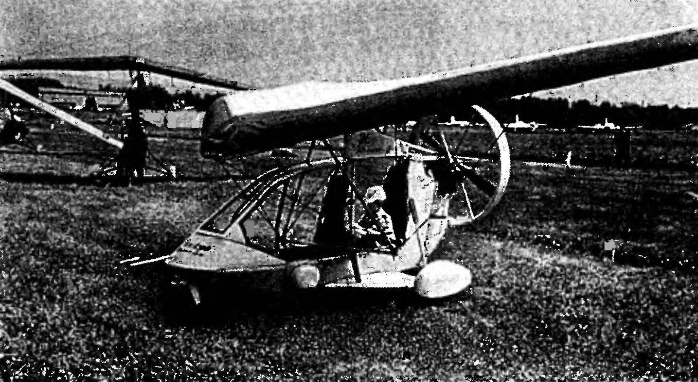 This small aircraft drew more attention to themselves at the Tushino international salon in June 1995. It differed from other such somewhat unusual layout. In conversation with its creators revealed that this design decision was made as a result of deep theoretical and experimental work conducted by the authors in the field of aerodynamic interaction of the wing and the propeller trikes. Learn more about your child we asked one of the designers of the project “Comet” and the pilot S. Sitdikova.