Rectangular frame made of steel angle 30×30 mm. After completion of the receiver it is welded to its hull.
The layout of the parts and components of your compressor you choose a classic — as the majority of these household units produced by industry. A basis (frame) for all sites and details was quite massive and bulky receiver — this is needed for Sparky motor-compressors under him organized a 50-liter bottle from under liquefied petroleum gas, designed for pressures up to 16 atmospheres. To get it is not too difficult: in many villages now gasification and cylinders become unnecessary.
From the container, removed the remnants of the propane. This is done in the following way. First turned the valve. Cylinder set “on end”, and above that is the container of water. Using a thin rubber hose with a metal tube on the end filled the cylinder with water which drove out not only gas, but also the remnants of foul-smelling liquid, which is added to propane to smell (to detect leaking gas).
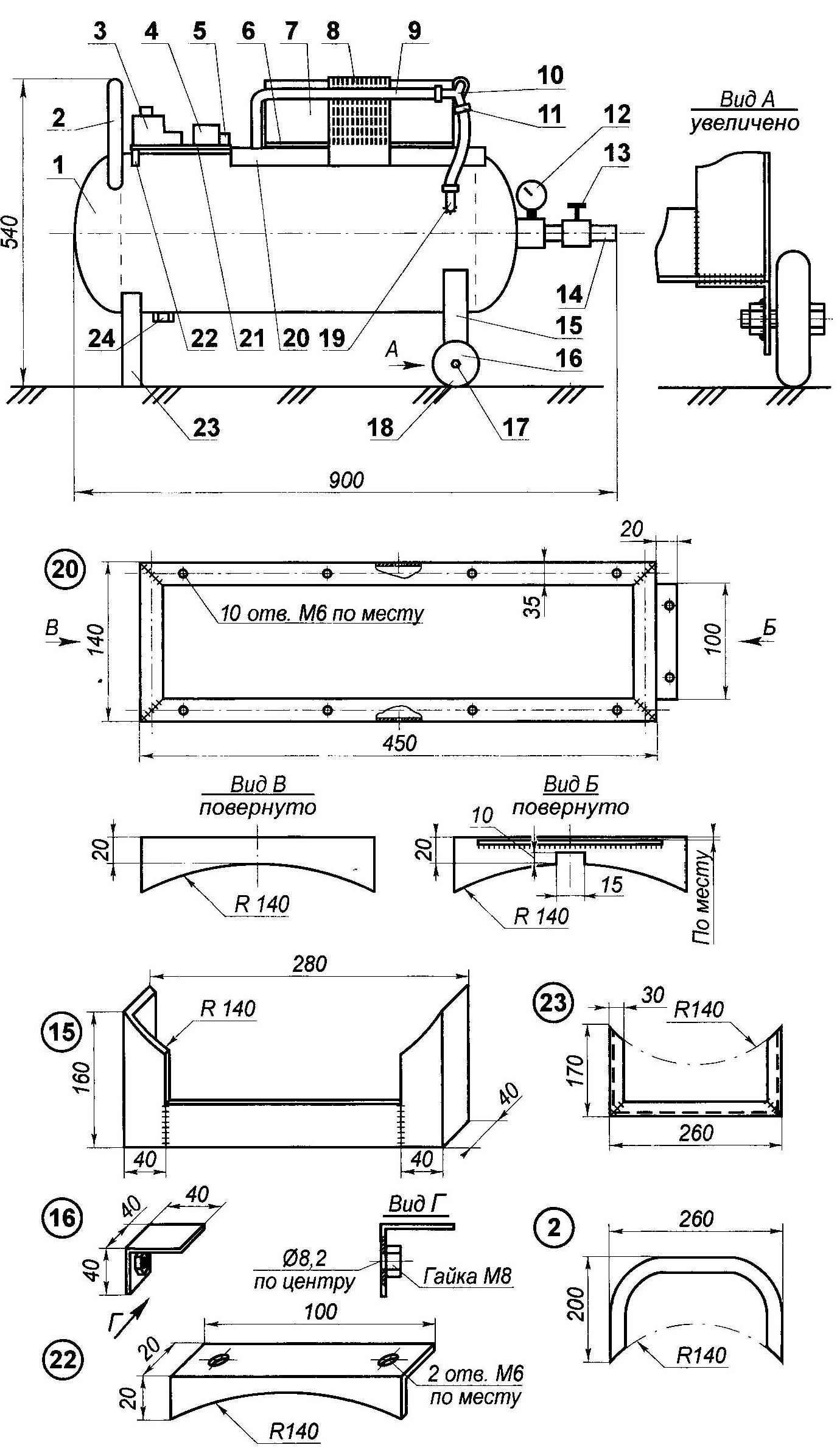
Compressor supercharger with two motor-compressors of household refrigerators:
1—the receiver (the gas tank capacity of 50 liters, modified) 2—handle (tube d20); 3—the starter (from washing machine); 4—relay (from washing machine); 5 — terminals (from fluorescent lamps); 6 — bracket fastenings of the motor-compressor to the frame (area 20×20, 4 items); 7 motor-compressor (from a refrigerator, 2); 8—mesh (kitchen cleaner); 9 — connecting tube (oxygen hose, 3 PCs.); 10—tee (steel pipe d7); 11—clamp (6 PCs); 12—manometer; 13 — valve; 14 — output fitting (pipe 010); 15 — the main (rear) rack (angle steel 40×40); 16 — an arm of fastening of a wheel (angle steel 40×40, 2); 17—the wheel axle (bolt M8 2 PCs.); 18—wheel (on the stroller); 19—inlet fitting (steel pipe, d10); 20—sub frame (steel angle 30×30); 21 —electric charge (Micarta s5); 22—front fee (steel area 20×20); 23—additional front receiver (30×30 area)
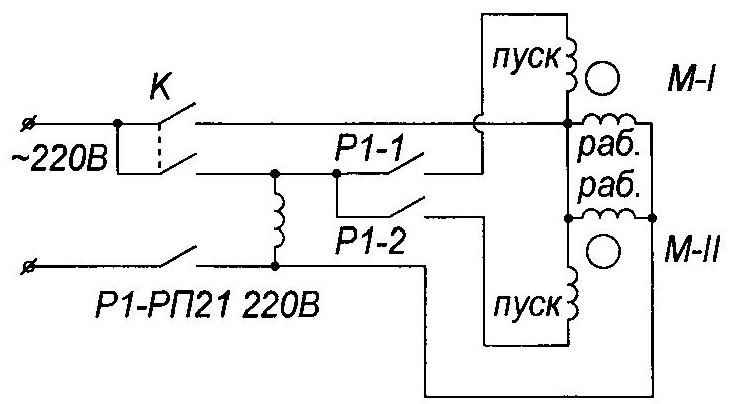
Electrical diagram motor-compressors
The balloon is removed the lower support ring, first cut it crosswise, and then the petals straight turns until, until they break off at the weld. Could the support ring and not to dismantle, but it would spoil the appearance of the product.
Before carrying out welding work, for security purposes, the container is again placed “on end” and again the brim was filled with water pair produced by welding in the area of heating would rise through the water to cool off and inside the container is not formed any explosive mixture.
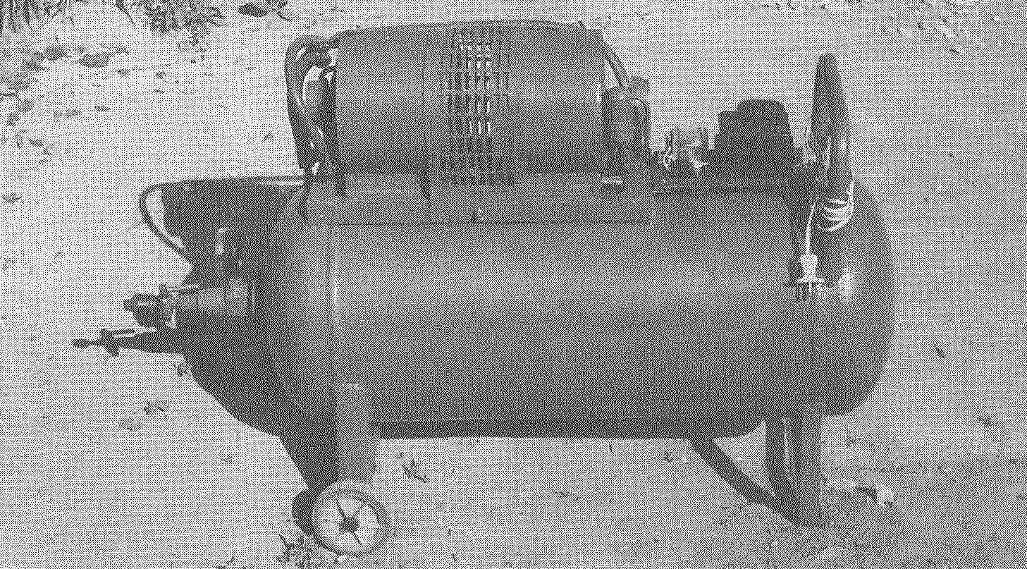
On the receiver top (so we can at least tentatively speak, because the receiver is cylindrical and is placed horizontally) placed a supercharger from paired motor-compressors (on my sub frame made of a 30×30 mm area) panel: contactor, relay and terminal block. Closer to one edge welded handle, curved from the water pipes with a diameter of 20 mm for the “relocation” of the unit. With the same purpose under the receiver failed chassis at one end (under the grip) — rack, shaped like an inverted letter P, and another similar rack, but with a Cola-sikumi (from the pram).
The first hour is made from a steel angle 30×30 mm, and the second (let’s call it main and first additional) area of 40×40 mm. To the second rack from the bottom is welded more on the edges of the rungs, angled mounting brackets with holes for the wheel axles. Coaxially to the holes on the inner side of mounting brackets (to their vertical shelves) welded nuts M8 for fastening axes of the respective bolts M8.
On the side of the cylinder in the wall of the drilled hole with a diameter of 8 mm and is welded coaxially to the input fitting is a small section of pipe with a diameter of 10 mm. is connected through a hose with one of the tap tee. Two other drainage are connected to the same hoses (oxygen, high pressure) with branch pipes nozzles of each of the motor-compressor. Hose connections, fittings and tee tightened clamps.
To remove from a container in the operation of the water and oil another short pipe with thread on the end welded on the bottom of the cylinder, also drilling a hole in the wall of the internal pipe diameter. The choked fitting screw-on stopper.
Brass valve at the end of the cylinder is also being finalized. First, in his case the hole is drilled and tapped M14. Here screwed pipe, and to it using the special nut is attached to the manometer. Another pipe screwed into the outlet valve — it is connected the hose consumer.
The electrical part of the compressor consists of a starter (from the washing machine), cut-off relay starting windings (also from the washing machine) and Kremnica the wire connections (from the fluorescent fluorescent lamps). They are all mounted on a single Board of 5 mm of the PCB and mounted to the top of the cylinder. One end of the Board rests on the shelf frame motor-compressors, and one on one support-rack, welded to the container.
Nutrition — from the household AC mains voltage of 220 V. the Electrical circuit and separate actuators allow you to enable or any one of the two motor-compressors, or both, depending on compressed air consumption by the consumer.
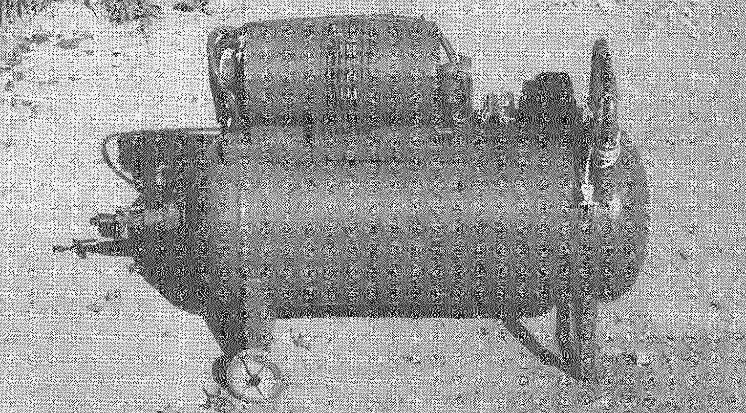
And again. In the process of operation is out of order regular the valve of the gas cylinder (now reverse). And had to be replaced. The same valve was not, and therefore put a suitable crane from the liquid cooling system of the car “Moskvich”. The compressor with this valve and pictured.
A. PEVNEV, Dimitrovgrad, Ulyanovsk region.
Recommend to read
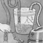 VACUUM-PUMP
If you add to the cleaner plastic bucket, the lid of which made two holes, the diameter of the respective pipe cleaner, by inserting in the same hole crimped hose connected to the vacuum... Shoe rack with seat
You know that feeling when you open your apartment door and immediately run into a mess of sneakers, slippers, and a pair of boots that simply have nowhere to go? That was exactly our...
 Dear “modelist-Konstruktor”! In No. 9, 2004 your magazine published an article about made me the compressor on the basis of the motor-compressor from the old refrigerator. Have used it for years for various uses: for paint spraying, tyre inflating of wheels and other works. Just not enough pressure and air supply. And then came the idea. To make the apparatus more and more powerful with two (paired) motor-compressors. Finding them was not difficult — now carried out of apartments (and simply thrown into the street) working refrigerators, which, so to speak, out of fashion.