For sale is a lot of models of tillers from the miniature “odnozalnyh” to an impressive— for a dozen and more horsepower, both imported and domestic production. But even our units are not cheap, because this purchase was not carried out, but without the tillers left.
Re-checking the filing of the magazine “modelist-Konstruktor”, selected and examined several publications on the topic of self-production of tillers. Convinced that “not gods pots”, and believed in their strength that can make a similar unit myself, good experience of a homemade design I already had. Was in there a no metal cutting tools, welding machine, and most importantly — although not new, but working the engine from a cargo scooter. He determined the basic dimensions and layout of the tillers, the parameters of transmission, a set of working bodies.
For design of motor-block — design based on existing power units, auxiliary equipment and materials it took about a month. At this stage, and determined what parts are to be ordered for them had complied with the relevant sketches.
Over the winter, just in time for spring field work managed to build a mechanical assistant and immediately try it out. The car my expectations were mostly met, though not 100 percent, but this will tell later.
The layout of the cultivator is such that all units are based on the frame. Spatial frame, made for a simple dvuhlonzheronnoe (duplex) scheme, only the front and rear spars are bent up. While their front ends are bent more toward each other and welded together and to the rear ends welded to the wheel (taken along with the control levers of a motorcycle “IZH”). The spars are made of steel water pipe outer diameter 32 mm. in the front junction of the side walls along the length are connected by several cross members. Some crossmember “part-time” performs other functions (for example, the front cross-member serves as a stop for the chain tensioner of the first stage of transmission) or, conversely, details of other purposes are used and the crossbars (as the area under the battery).
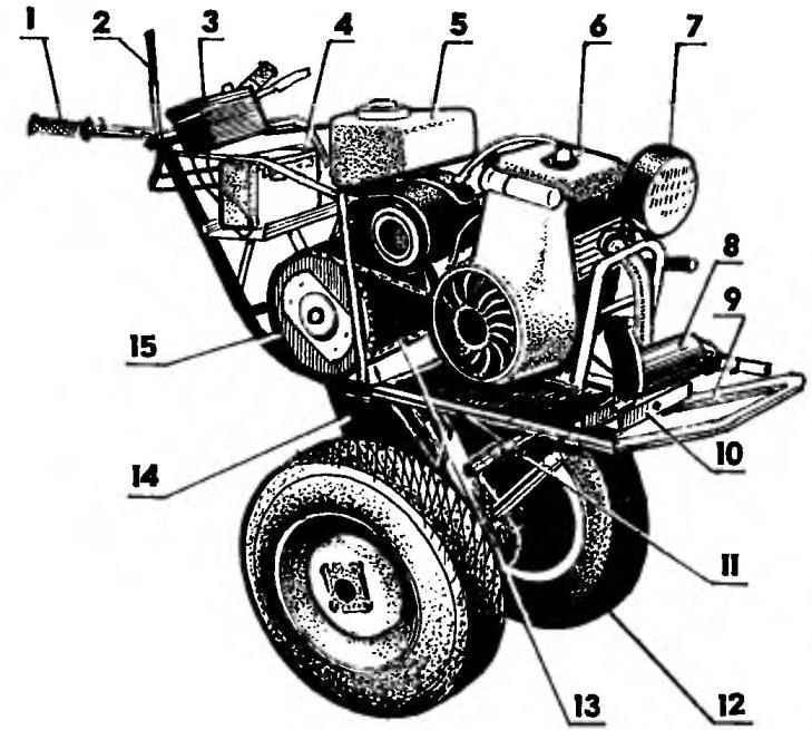
Tillers:
1 — the wheel (from a motorcycle “IZH”); 2 — the lever of switching of speeds; 3 — dash unit; 4 — battery; 5 — fuel tank (3 l); 6 — motors (motor scooter cargo “the Ant”); 7— headlight (automotive); 8 — damper; 9 — frame; 10 — the emphasis of the tensioner; 11—slides; 12 — wheel (sidecar SMZ, 2); 13 — circuit of the first stage; 14— second gear stage; 15 — sprocket driven first stage
Sub frame:
1 — the runner of the sled (area 40×40, 2); 2— rear cross member; 3 — ridge (steel pipe 1 1/4″);4—bracket-clip (St3, strip 50×4, 3). 5 — the middle cross bar: 6 — front cross member; 7 — traverse (32×32 area);
Frame:
1 — the wheel (from a motorcycle “IZH”); 2 —bracket instrument panel (25×25 area); 3 — a platform and mounting bracket rechargeable battery; 4 — spar frame (pipe d32); 5 — Carter the chain transmission of the second stage; 6 — under engine frame; 7 — chain tensioner of the power transmission of the first stage (M10); 8 —emphasis chain tensioner; 9 — brace (pipe d22); 10 — bracket attaching cultivator-tion of the subframe (milled channel No. 8); 11 — bracket attaching the transport cart; 12—crossbar(полоса30х4,3 PCs.)
Dimensions and fixing points power unit
To detail frames can be attributed to the gear case, which acts as a strut between the powertrain and chassis of the cultivator. To the crankcase at the bottom rear is welded couplings for attachment to the cultivator or hoe subframe-axle truck. Along with the latest walk-behind tractor is converted into a cargo vehicle.
As mentioned in the beginning, as the power unit used engine from scooter cargo “the Ant”. The two-stroke engine, gasoline, 13 HP with forced air cooling, which is very desirable. Otherwise, this device would still produce — even in the transport version the speed of the walking tractor is small, and therefore, an overheating engine would have been inevitable. Transmission four-speed mated to the engine. Motor homemade silencer — steel pipe with a diameter of 70 mm and a length of 250 mm with the exhaust hole 16 mm, filled with metal shavings. Complex configuration of the exhaust path due to the arrangement of tillers and the need to exhaust to the side.
The power unit is mounted on under engine frame, which is a slide with welded cross members to their arc of water tubes of an external diameter of 42 mm. To the ends of the arc and in the median part welded brackets, clamps. The holes in the mounting brackets under the M8 bolts were drilled in place in accordance with the holes in the ears on the crankcase of the engine. Then, the arc side of the cap installed and privatives welded to middle cross member skid. Extreme cross were brought under the arch, bowing, and the middle of them and even to extort the place so that the line of contact with the arc was the entire width of the crossbars. Then arc welded to the cross members along lines of contact, and the ends of the crossbars to the rails of the sled. Guides made of angle steel 40×40 area. To the front ends of the guides of the slide top cross member is welded. In the middle of its vertical shelves drilled hole for M10 screws With this bolt inserted also in front of the cross frame, while operating the walk-behind is the chain tension (t = 12.7 mm) from the first stage reducer. The ability to move the slide on the side members provide four longitudinal groove (two for each runner). Through these grooves under engine frame secured to the main frame with four bolts M10.
Chain reducer. To reduce speed and increase torque transmission from the output shaft of the power unit to the propeller (wheel or Ripper) in the transmission system used a two-stage chain gear. The first stage consists of 17-and 57 bevel-bevel stars. Step of their teeth as well as the links connecting them chains, Leading to 12.75 mm (17-bevel) asterisk planted on the output shaft of the power unit, the led mounted on the outer flange of the input shaft of the second stage. The second stage of the reducer is operating in more severe conditions, reinforced, has a step of teeths of sprockets and chains 19,05 mm. From the sprocket 11 teeth, the driven — 25. Because this stage is in close proximity with the processed and because of the dusty soil, it is placed in a closed crankcase, which is mounted between the two crossbars and frame rails, and welded to the first directly and the second through the steel spacers. For reliability between Carter and one of the cross bars installed and welded brace.
The second stage of the chain reducer (breakdown by Carter):
1 — case (channel No. 20); 2 — cover (St3, sheet s5); 3 — gasket (oil resistant rubber); 4 — sprocket of the second stage (z= 11, t= 19,05); 5— a key; 6 — a bearing 206 (2); 7 — compensating bushing; 8 — shaft; 9 — nut M22x1. 5 spring washer; 10 — gland; 11 —distance sleeve with a keyway; 12—eccentric bearing carrier (St3, 2); 13 — screw M8 with spring washer (30 PCs.); 14 — sprocket driven second stage (z = 25, t = 19,05); 15— bearing 3008 (2 PCs); 16 — bearing; 17 — a sealing bushing; 18 — left axle shaft; 19—drain plug oil (screw M10); 20 — the bottom of the case (STZ, sheet s4); 21 — plug, oil (screw M10); 22,23 — oil seals (2 PCs); 24 — the right drive axle; 25 — M6 fixing screws (8 PCs.); 26 — bolt M8; 27 — chain t = 19,05; 28 — sprocket driven first stage (z = 57, t = 12,7); 29 — remote sleeve
Hoe subframe:
1 — traverse; 2 — bracket (2 PCs); 3 — M12 (3 pieces); 4 — mounting cross member (area 30×30,2 PCs); 5 — M8 screws (4 PCs); 6 — ridge; 7 — a coupling device (channel № 6,5); 8— M8 screws of fastening of a stretcher (2 pieces); 9— counterpart of the coupling device (milled channel No. 8: the size between the shelves 65 mm); 10 — the earring to attach the truck; 11 — the gear unit; 12 — pin (tube d22 with thread M22 nut M22), parts 1,2,6 made of steel rectangular tube 60×40
The housing of the second stage chain gear:
1 —ears of the locking device; 2 castle; 3 — card loop; 4 — gasket; 5 — side panel (2); 6 — bottom
Lugs are placed on the tires of the wheels in the cultivation of the land for a better grip with the ground, and when operating the walk-behind tractor in the winter
Collapsible brace with cleats:
1 — semiring brace (steel strip 60×5,2); 2 — swivel hinge; 3 — castle grouser; 4 — cross gruposura (25×25 area, 11 items); 5 — diagonal grouser (shelf area, 12 PCs); 6 — bolt M8 locking device (2); 7 — return half of a locking device (25×25 area)
Carter is welded from two pieces of steel channel No. 2, which sprezarkowni along the length of the shelf to a height of 35 mm. In the lower part of the walls of channels made in the form of a semicircle, and the shelves of cut. Instead, the bottom is welded from 4 mm sheet steel, full in the form of a half-cylinder on the semicircles of the wall. On top of the crankcase is closed with a lid with a gasket of oil-resistant rubber. Both walls are made by two coaxial holes with a diameter of 100 mm under the bearing housing and around each of them — six “orbital” (at the same distance from the edge of the circumference and with equal spacing between them) tapped holes M8 for fastening the housings to the crankcase.
The lower bearing (axle) is common, and the upper (shaft) — eccentric. By rotation around the axis (speed, minimum 15°) is adjusted chain tension second stage of the gearbox.
The shaft of the second stage gear rotates in two ball bearings 206. The drive sprocket is connected to the shaft of the prismatic key and fixed inside the case in the middle between its two walls, the spacer bushings. Biggest driven sprocket seated on the centering boss on the right axle and fixed between opposite flanges of both axle shafts with six M8 bolts. Lower teeth sprocket with multiple chain links immersed in the oil bath. When driving walking tractor chain carries oil to the top of the crankcase, lubricating, thus, all the rubbing parts of the second stage. So the oil from leaking out, all bearing set oil seals
A rigid flange connection forms a of the axle like a single shaft rotating in two ball bearings 308. At the ends of the axle shafts are made slotted cutting through them, the torque is transmitted to the wheels or rippers.
Wheel tillers with tire size of 5.00—10″ motorized SMZ rippers homemade. For the best coupling of wheels with the soil in cultivation of the soil, and also the operation of the tillers in the winter on the tires wheels put on a makeshift bandage with the grouser. The bandage is manufactured from a steel strip section 90×5 mm, lugs — corner 25×25 mm. Below the bandage is not slipping with the tires on corner grantsearch left antennae, cut on their sides of the vertical shelves. Antennae bent inside bandage wrap and cut parts welded to it obliquely between the corners. For easy mounting on the tire rim Hoop made of a composite of two halves connected on one side by a hinge, and the other, a locking device made according to type of what is on the cover of the gear housing.
Behind tractor equipped with rippers (mills) n one cultivator Lanka to create a braking torque. Traverse stump vtorogo subframe disconnected
Rippers (mills). Treated with their help, the soil becomes soft, with a smooth surface, and does not require subsequent harrowing
Assembly elements of the Ripper:
a — splined bushing with four flanges and the end panel; b — knife with a cutter (16 PCs.)
As the undercarriage of the trailer talikn ispolzovali the front axle of the sidecar Assembly
Power frame trailer truck:
1 — main frame (steel, pipe 60×30); 2 frame the platform edging (steel, 25×25 area); 3 — additional ties and struts (tube 1/2″, angle 35×35); 4 — seat; 5 — pole (a steel rectangular tube 60×30); 6 — swivel hitch; 7 — (steel rectangular tube 60×30, 2 PCs.)
For the installation of cultivators tillers produced arable sub-frame of rectangular tube 60×40 mm. It is compound, has a T-shape, detachable cross member.
The frame can be installed one, two or three cultivator foot. These items are factory-produced, picked up on the “cemetery” of agricultural machinery. At the front end of the subframe is welded to the coupling device, made of a channel number of 6.5.
When connecting the subframe to the tillers of the last is inserted into the bracket (channel No. 8 with milled shelves — the size of 66 mm between them) on the frame (gear case), and both parts are connected with M8 bolts through the corresponding holes in both parts.
Originally planned to use the block to work with odnoimennym plow, which is also made by myself. Subsequently, however, this had to be abandoned — the work was slow and required a lot of physical effort.
Instead of the plow for tillage produced two cultivator (cutter). They are installed to work in place of the wheels.
Ripper is a set of knife cutters, fixed with M8 bolts on the flanges, fitted and welded to the sleeve. The inner diameter of the sleeve slightly larger than the diameter of the splined part of the axle shaft. Knives are made from steel strip 50×60 mm, the cutters taken from the cutting parts of discarded mowers.
For land cultivation cultivator with rippers in the subframe need to install one or two feet to create a braking torque. Then the rippers, rotating, spin, burrow into the soil and break it up into small fractions. Adjustable braking torque by setting a different number of legs and degree of embedding them. When well adjusted by the time the tillers are uniformly moving forward myself and a farmer-operator easily controls them. If the treated area has climbs and descents, the braking torque will have to be manually adjusted, the level of immersion of the blades into the ground due to the effort on the steering wheel.
The depth of tillage Ripper about 200 mm is just the height of bayonet spade. The soil after loosening becomes soft, with smooth surface, and does not require harrowing.
As mentioned in the beginning, tillers can convert into a towing vehicle to transport cargo. To this end, I have made for him a two-Wheeler semi-trailer truck as its suspension utilized front axle of the motorized Assembly (with the wheels).Main frame made of steel rectangular tube 60×30 mm dvuhlonzheronnoe scheme with two crossbars. In front the longerons converge, and in this place assembled seat.
Pole carts are made stepwise to bring the coupling device as close as possible to the axis of the wheels. This makes it easier to control — like machines with articulated. Stage drawbar reinforced struts of half-inch pipe. From the bottom to the drawbar welded on foot pegs. The coupling device is simple, made according to the type of swivel to the cultivator on rough roads or slopes were able to be turned relative to the horizontal longitudinal (conventional) axis. On top of the main frame is mounted the frame-trim the cargo platform, made of steel area 35×35 mm.
Bogie frame is connected with the levers by means of axle stands from the same pipe, and frame. Stand is reinforced with struts.
Platform frame with tongue-and-groove boards with a thickness of 25 mm. I to the platform to make a removable or hinged side.
Electric walk-behind 12-volt. The battery consists of two batteries 9МТ-14. The generator at 90 watts. Coil ignition and electric start — full-time. Headlight — car.
A. NORVATOV, In o l s s K, the Saratov region
Recommend to read “DRAGON III” The sounding rocket "Dragon III" — two-step. The engines of both stages is solid. The mass of the fuel engine of the first stage (start) — 686 kg. the rocket Starts with the ramp... SPEED THROUGH SIMPLICITY We offer young athletes like high-speed cord combines the experience gained in this kind of automodelisme in recent years. Sorpresa design is logical from the point of view the sole...
Scroll back to top
 For cultivating soil in garden plots most appropriate mechanism to consider a walk-behind tractor. It has a small footprint and consumes few fuel, has the necessary agility and sufficient performance. The possibility of a quick change to some tillers tillers for others (e.g., plow cultivator, cultivator or Hiller), makes this mechanism almost universal. If necessary it can adapt even under the vehicle to transport goods for short distances on farm roads.