Grind on a hand grater even a dozen carrots – consuming affair, and if you want to prepare food for Pets to shred large quantities of vegetables, fruits? I came out with a simple electric grater. Used motor power of about 200 watts, with a rated shaft speed of 1400 rpm. (it will fit the engine from a household bench grinder; can be used three-phase asynchronous capacitor switching circuit in a single phase network.)
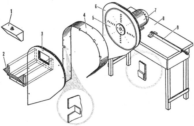
Working on the float is a round steel disc with a thickness of 1.5 and the outer Ø300 mm. the Cutting edges of the disk are formed by squeezing the edges of the holes Ø8 mm drilled in the disk in mutually perpendicular directions. Each row contains 5 holes arranged with an interval of 16 mm, and offset in the radial direction with respect to the next row by 1/2 of the interval. Thus, get two groups of cutting edges, completely covers the working area of 80 mm in width To obtain a different degree of size reduction of required disk with holes of a different diameter. The stiffness of the disk in the axial direction is reinforced by double rolling the edges, and the rear of the radial installation of four steel or dural corners.

 Grind on a hand grater even a dozen carrots – consuming affair, and if you want to prepare food for Pets to shred large quantities of vegetables, fruits? I came out with a simple electric grater. Used motor power of about 200 watts, with a rated shaft speed of 1400 rpm. (it will fit the engine from a household bench grinder; can be used three-phase asynchronous capacitor switching circuit in a single phase network.)