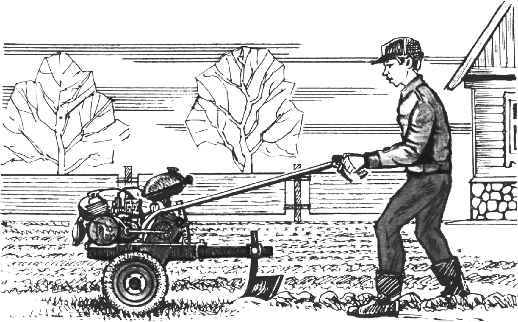
A small plot of land, where “serious” machinery has no room to work, can really only be cultivated properly with a walk-behind tractor. That is why a thrifty rural owner, having decided to get such a machine, will first choose its make and weigh its capabilities. And only then will he think about a cart, mounted and trailed implements that he will need for a specific job.
So it was in my case as well. The only difference is that I decided not to buy a ready-made walk-behind tractor, but to build one myself. As a model I took the design of the industrial “Lug”, which is appealing in its simplicity. But only as a model, because the assemblies and units I had differed noticeably from those used on the prototype. They had to be adapted, and many units and parts had to be made from scratch.
But before starting fabrication, I sketched out something like a technical assignment for myself. In the first point I specified the main task of the walk-behind tractor — tilling the soil by cultivation. In the second — I outlined the range of mounted implements to be used — all of them were to be from the “Lug”. In the third — I planned for the walk-behind tractor to be able to work with a cargo cart.
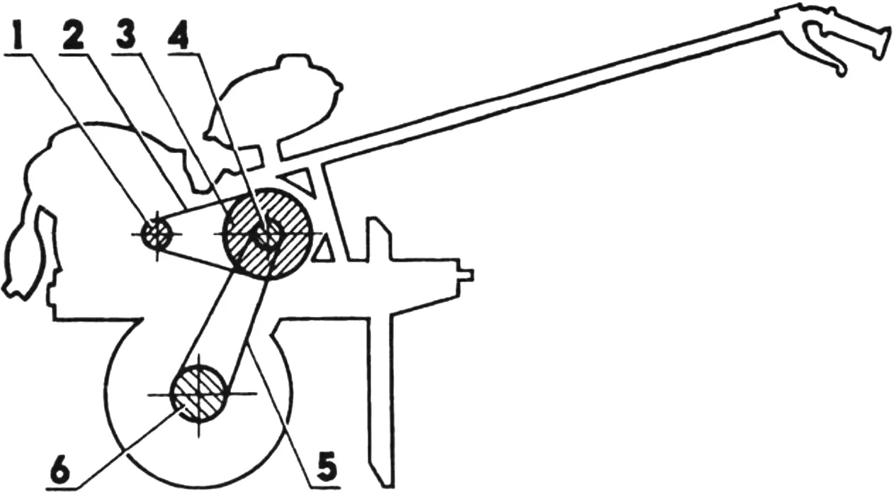
1 — drive sprocket (z = 14, t = 12.7); 2 — intermediate drive chain (t = 12.7); 3 — intermediate outer sprocket (z = 40, t = 12.7); 4 — intermediate inner sprocket (z = 14, t = 19.05); 5 — final drive chain (t = 19.05); 6 — final drive sprocket (z = 27, t = 19.05).
The MP-2 (as I named my creation) turned out splendidly. After acquiring the skills of handling the “em-pee”, it became clear that it is fairly simple to operate and reliable in use. Still, I think explanations of its design will not be superfluous.
As the power unit, a 12 hp engine with forced cooling from an MMVZ-3.112 motorcycle was taken. The units serving the engine were assembled, as they say, from here and there. For example, the ignition coil is a B-300, the electronic switch is a KET-1A, the air filter is from an MMVZ-3.112 motorcycle, the muffler is from an MP-800 motor pump, the fuel tank is from a “Riga-12” moped, the throttle lever is from a “Buran” snowmobile, and so on.
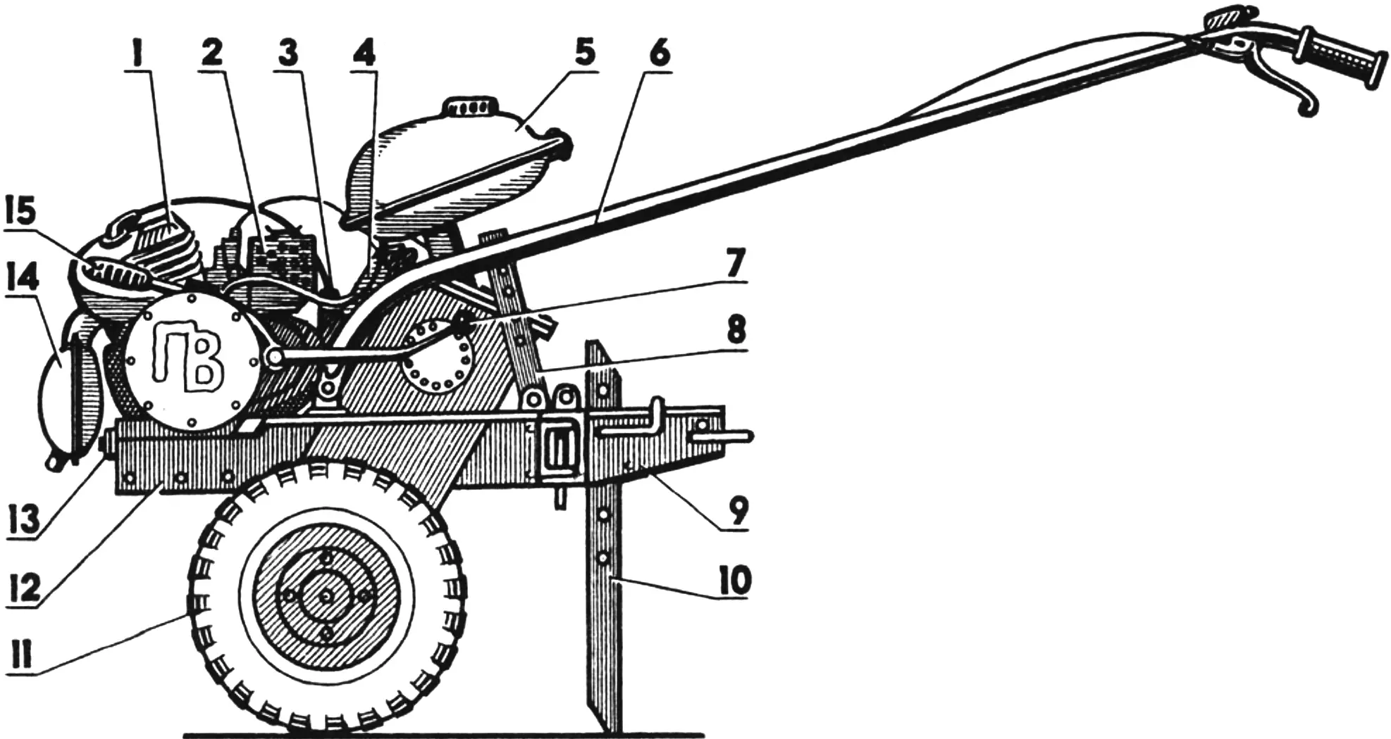
1 — engine (from an MMVZ-3.112 motorcycle); 2 — air filter (from MMVZ-3.112); 3 — ignition coil (B-300); 4 — electronic switch (KET-1A); 5 — fuel tank (from a “Riga-12” moped); 6 — steering bars with throttle and clutch levers; 7 — engine gearbox lever; 8 — bar position adjustment plate (2 pcs.); 9 — parking stand bracket; 10 — parking stand; 11 — wheel (2 pcs., from a “Muravey” motor scooter); 12 — walk-behind tractor frame; 13 — drive chain tensioner bolt; 14 — muffler (from an MP-800 motor pump); 15 — engine starting lever.
All of this is arranged on the walk-behind tractor frame, which is a rigid housing with side members (longerons). The frame is made of 4 mm sheet steel by electric welding. First, openings for the bearing housings of the intermediate and final shafts were cut in the side walls of the housing. In addition, the inner edges of the openings were reinforced with steel rings 5 mm thick. The combined thickness of the wall and the ring is sufficient for cutting a thread for the M8 bolts that fasten the bearing housing. All housings are fitted with gaskets and, except for the upper left one (in the direction of travel of the walk-behind tractor), with lip seals.
The upper housings are machined with offset bearing axes, which makes it possible to adjust the final drive chain tension by turning them. These housings have 32 fastening holes each for M8 bolts, but only four of them are used.
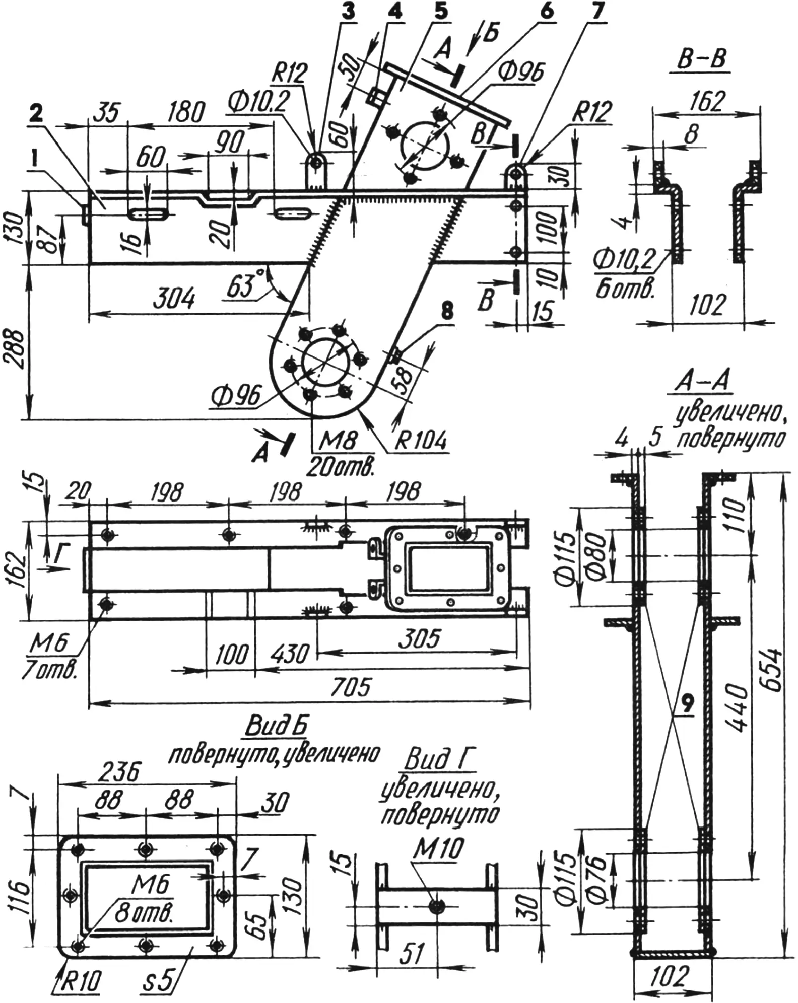
1 — stop for the intermediate drive chain tensioner bolt; 2 — side member (2 pcs.); 3 — lug for fastening the adjusting plate (2 pcs.); 4 — lug for fastening the electronic switch (steel, strip 20×3, 2 pcs.); 5 — final drive housing; 6 — flange; 7 — lug for fastening the steering bar (2 pcs.); 8 — oil level check plug (M14 bolt); 9 — reinforcing rings.
The intermediate shaft carries two sprockets: on the outside a large one with tooth count z = 40 and pitch t = 12.7 mm (from an MMVZ-3.111 motorcycle), and on the inside a smaller one with tooth count z = 14 and pitch t = 19.05 mm. The final shaft has one sprocket (z = 27 and t = 19.05) that runs in an oil bath. Transmission oil is poured into the housing from above; its level is checked through an opening in the rear wall of the housing (with the cover removed and the threaded plug unscrewed). The air pressure difference that arises when the chain drive is running is equalized by means of a throttled breather hole in another plug screwed into the housing cover. The latter is a complex combination of the cover itself, which is fastened with eight M6 screws to a flange made of 5 mm steel sheet on the upper edge of the housing, and the fuel tank frame welded to it. Such a combination is advantageous because, first, space is saved and, second, fuel from the high-mounted tank flows to the engine by gravity.
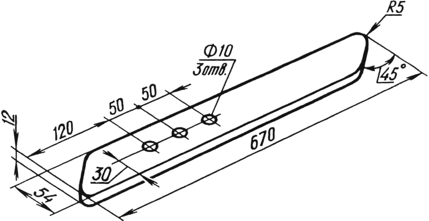
The side members of the walk-behind tractor frame, made as angle sections with the vertical walls removed where they join the inclined housing, are welded flush to it. The side members carry several structural elements: at the front — a stop for the intermediate drive chain tensioner bolt; in the middle — lugs for fastening the plates that adjust the position of the steering bars; at the rear — lugs for fastening the bars themselves. In addition, the horizontal flanges have seven M6 threaded holes for fastening the fenders.
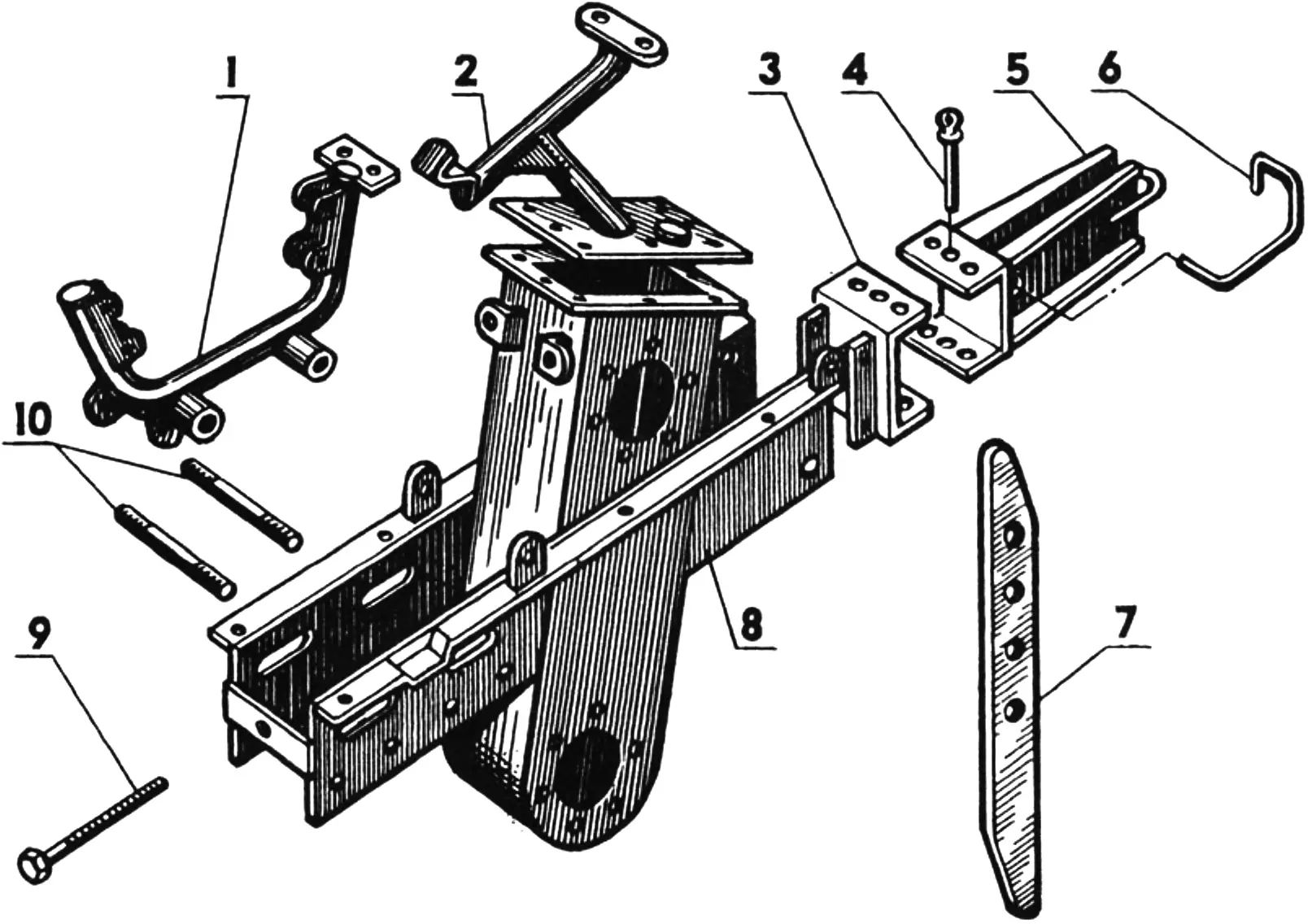
1 — engine frame; 2 — fuel tank frame with final drive housing cover; 3 — hitch clevis; 4 — connecting pin; 5 — parking stand bracket; 6 — parking stand lock; 7 — parking stand; 8 — walk-behind tractor frame; 9 — tensioner bolt M10x1.5 (L100); 10 — M16 studs (L130) for fastening the engine frame.
In line with the axis of the tensioner bolt, four slots for the engine frame fastening studs are made in the side members; these allow the studs to move forward and back within the slots and thereby change (adjust) the chain tension.
At the rear, holes are drilled in the vertical flanges of the side members for fastening the hitch clevis. This clevis, the support plate bracket attached to it, and the plate itself probably need no description — everything is clear from the drawings.
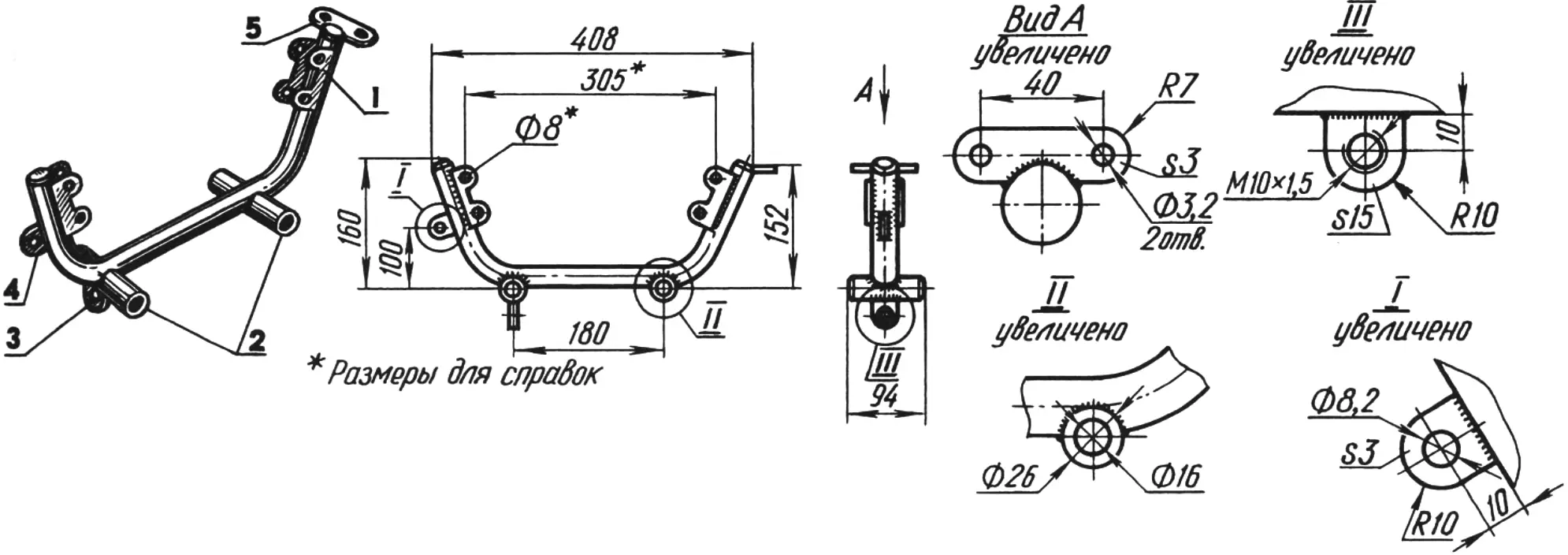
1 — part of the stock frame of an MMVZ-3.111 motorcycle with engine mounting points; 2 — frame mounting bushings; 3 — chain tensioner nut; 4 — muffler mounting bracket; 5 — ignition coil mounting bracket.
The engine frame is a part of a Minsk motorcycle frame, supplemented with two bushings for the mounting studs, a muffler bracket, a chain tensioner nut, and an ignition coil mounting bracket.
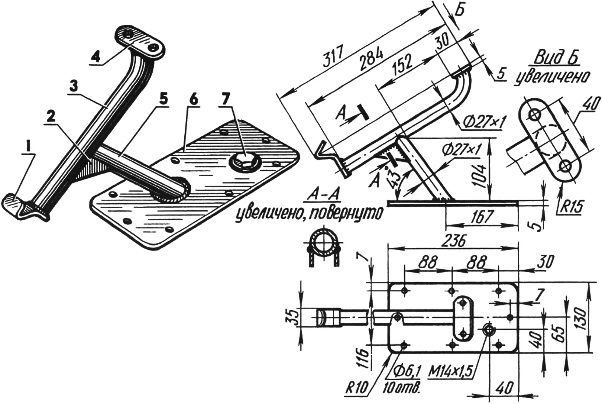
1 — tank fastening clamp; 2 — reinforcing pad; 3 — cradle; 4 — tank mounting bracket; 5 — post; 6 — final drive housing cover; 7 — plug with breather (M14x1.5 bolt).
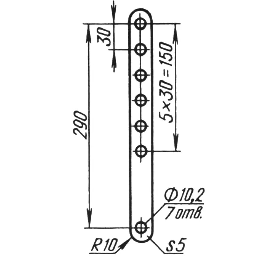
The steering bars are welded from pieces of tubing 27×1 mm in diameter and bridge plates of sheet steel 2 and 5 mm thick. The left bar carries the clutch control lever, the engine “stop” button, and a bracket for the adjusting plate; the right one carries the throttle lever, a device for adjusting the control cable tension, and a bracket for the second adjusting plate. In addition, the ends of the bars are fitted with rubber grips.
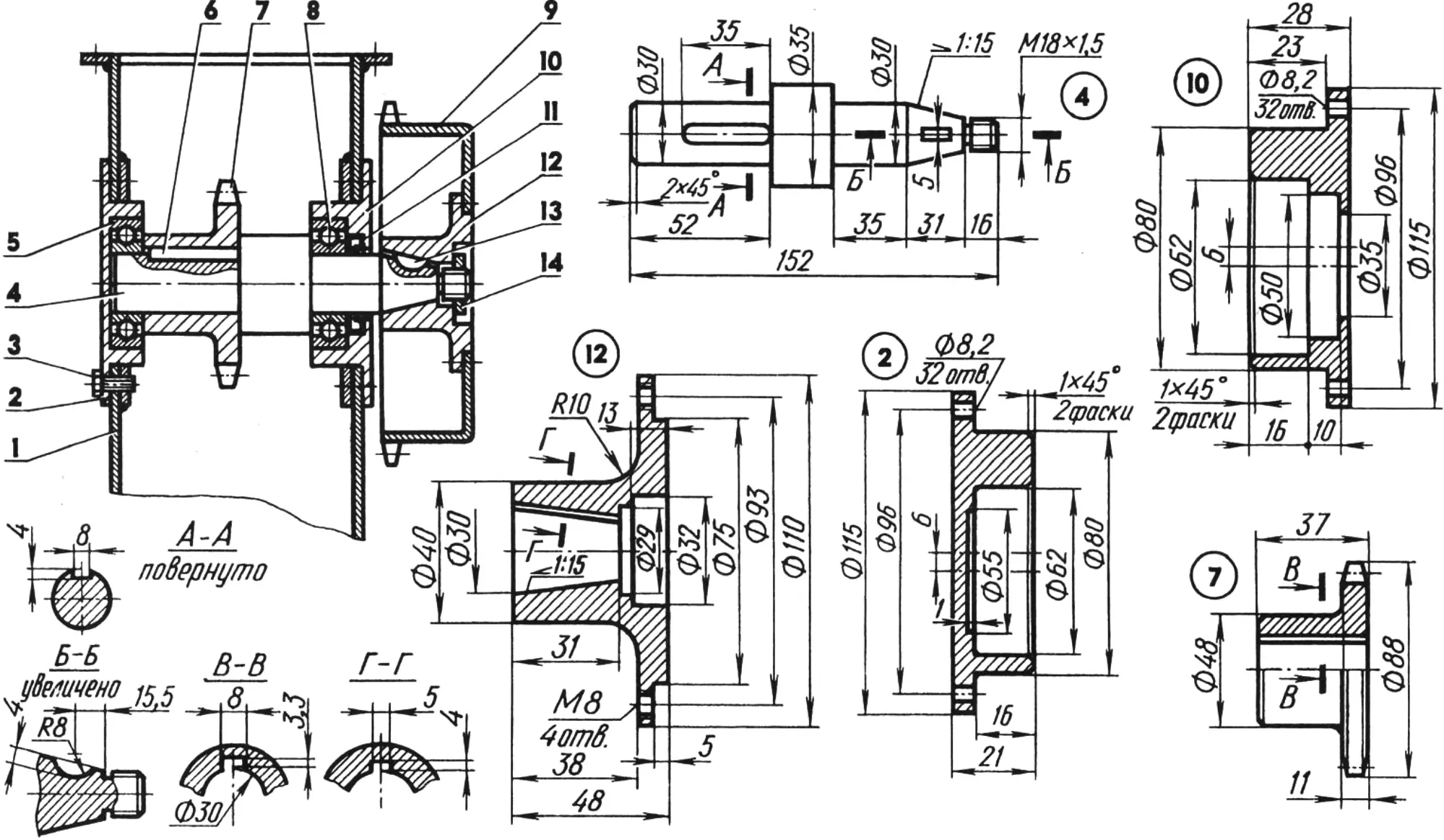
1 — final drive housing; 2, 10 — bearing housings; 3 — M8 screw (2×4 pcs.); 4 — shaft; 5,8 — 206 bearings; 6 — rectangular key; 7 — inner sprocket (z = 14); 9 — outer sprocket (z = 40, from an MMVZ-3.111 motorcycle); 11 — lip seal; 12 — flange; 13 — Woodruff key; 14 — M18x1.5 nut.
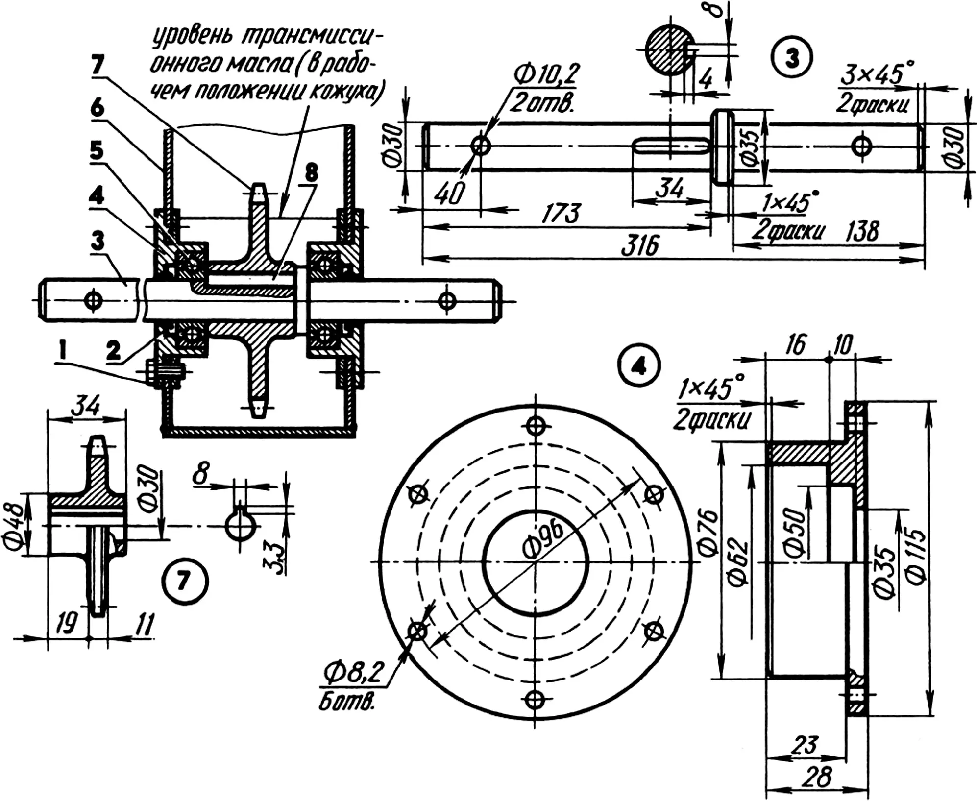
1 — M8 screw (2×6 pcs.); 2 — lip seal; 3 — shaft; 4 — bearing housing (2 pcs.); 5 — 206 bearing (2 pcs.); 6 — final drive housing; 7 — final drive sprocket (z = 27); 8 — rectangular key.
The engine gearbox shift lever is 250 mm long. At first, gears were shifted by hand using a special lever and rods mounted on the left bar. But later I abandoned that clutter. It turned out that gears are more convenient to shift… with the foot!
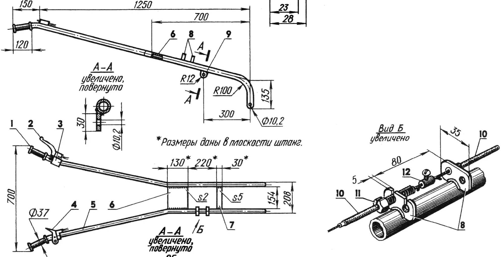
1 — grip (rubber); 2 — clutch control lever; 3 — engine “stop” button; 4 — throttle lever (from a “Buran” snowmobile); 5 — steering bar (tube 27×4); 6,7 — bridges; 8 — lugs for adjusting control cable tension; 9 — lug for fastening the adjusting plate (2 pcs.); 10 — cable ends in sheath (the second cable is not shown); 11 — M8 adjusting bolt (locknut not shown); 12 — clamp (Ø10×4 bushing with an M5 screw).
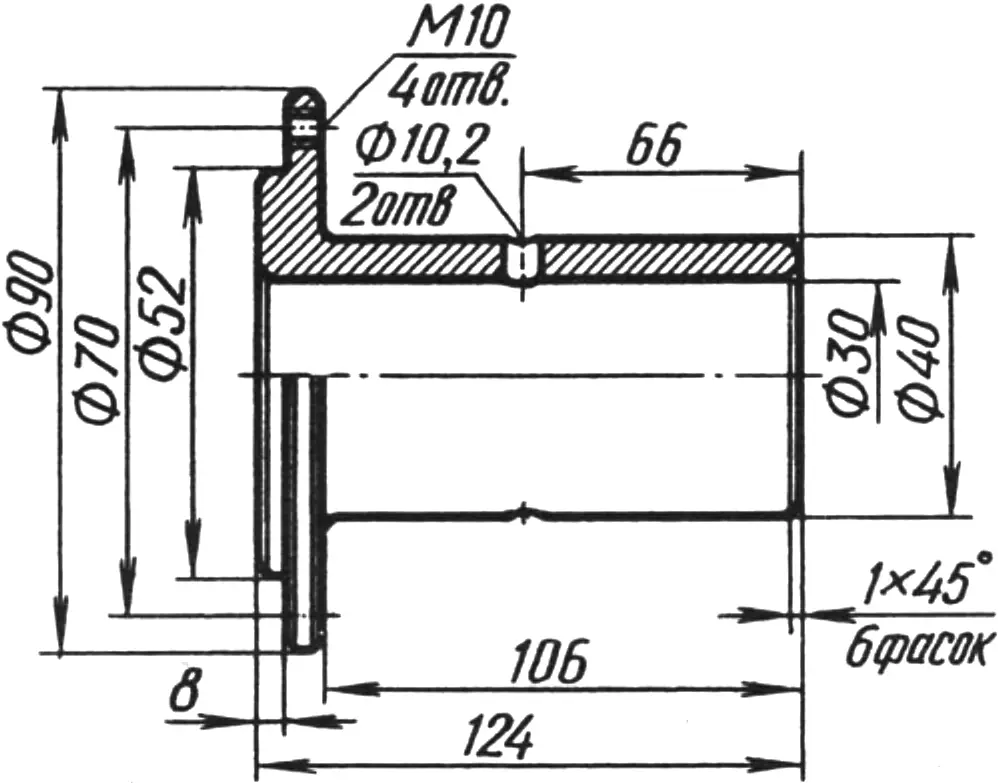
On the way to the garden or in the draft version, the walk-behind tractor moves on wheels from a “Muravey” cargo motor scooter. The wheel hubs are machined from steel blanks of suitable size and are each fastened to the final shaft with only one M10 bolt.
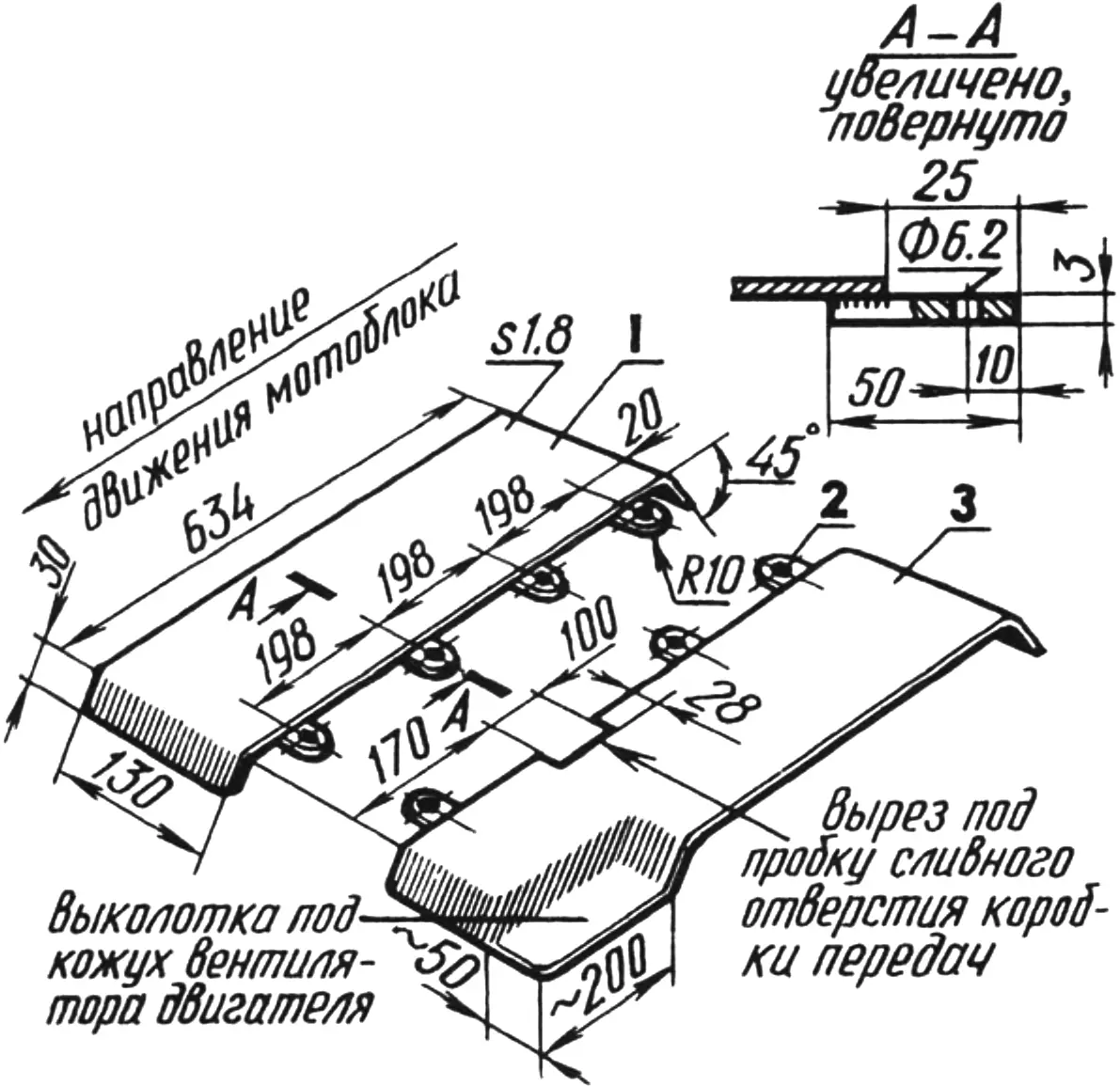
1,3 — right and left fenders (steel, sheet s1.8); 2 — hinge for fastening to the walk-behind tractor frame (steel, sheet s3).
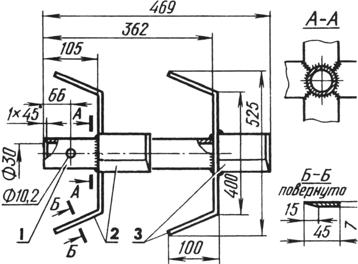
1 — body (tube 40×5); 2 — inner cutters; 3 — outer cutters.
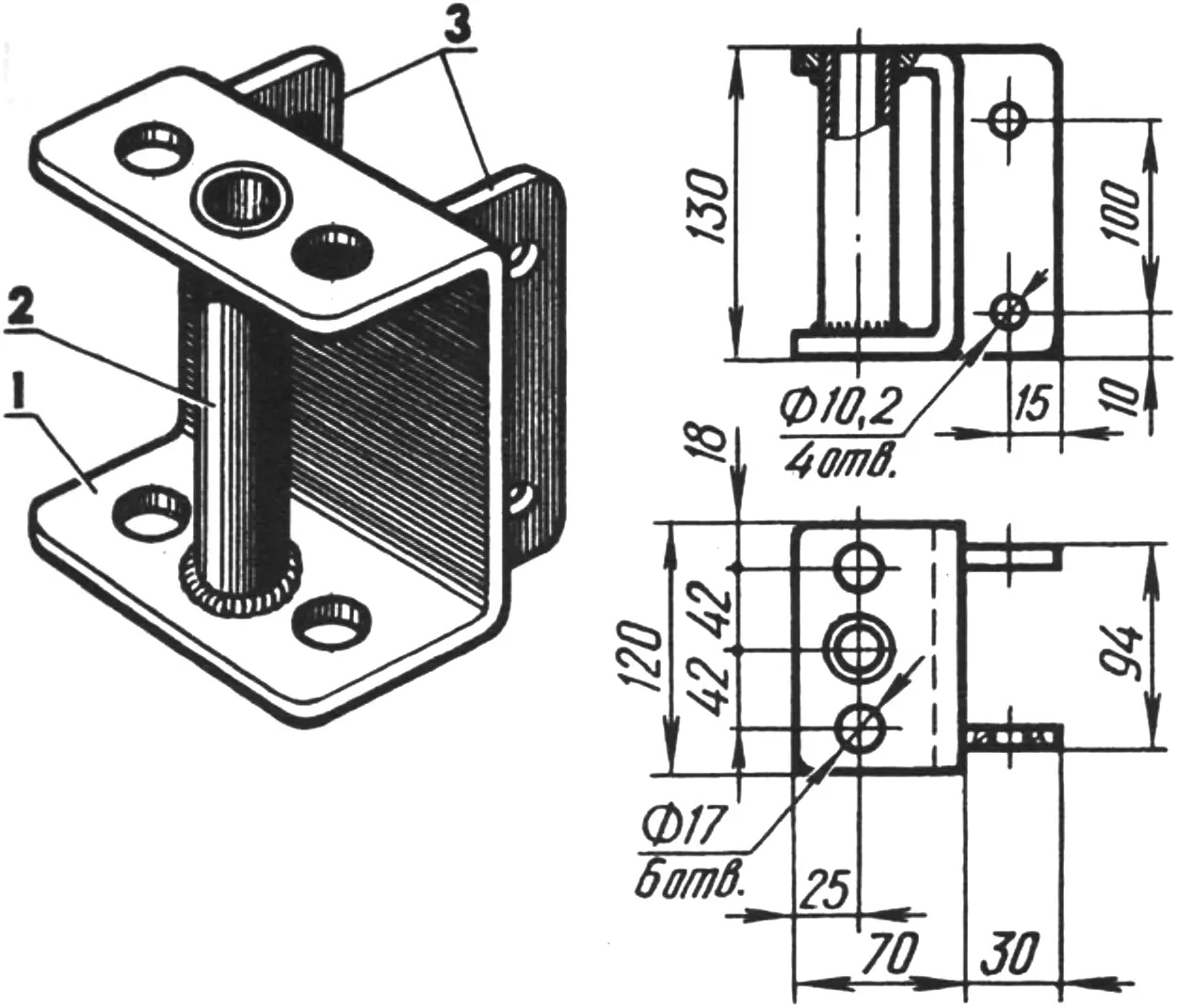
1 — body (steel, sheet s5); 2 — eye (tube 21×2, L120); 3 — cheeks for fastening to the walk-behind tractor frame (steel, sheet s5).
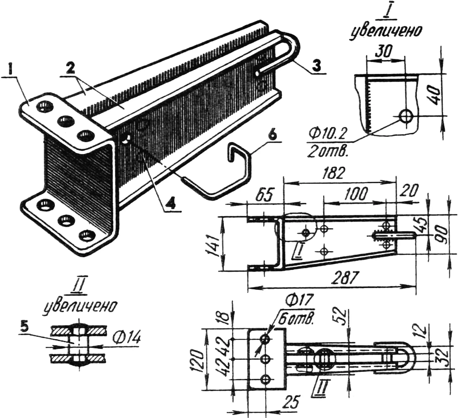
1 — body (steel, sheet s5); 2 — cheeks (steel, sheet s5); 3 — eye (Ø10 rod); 4 — electric rivet (8 pcs.); 5 — spacer (Ø14 rod, 2 pcs.); 6 — parking stand lock (Ø10 rod, dimensions — as fitted).
Before working the garden, for example before cultivation, the walk-behind tractor is “re-shod” — instead of wheels, homemade rotary tillers are fitted onto the ends of its final shaft. They are welded from bodies machined from pieces of tubing 40×5 mm in diameter, with cutters cut from GAZ-69 automobile spring leaves welded to them crosswise. The working width of such tillers in the soil is approximately 1 m.
I carefully prepared the finished walk-behind tractor for painting: I went over all sharp corners with a file, sanded the surfaces, and degreased them. Then I painted it twice. After that, my MP-2 has looked for several years like a factory-made machine. The walk-behind tractor is good not only in appearance — when working our gardens it is simply indispensable.
«Modelist-konstruktor» № 10’99, V. PETROV
Recommend to read
 Folding utility block
You can find all kinds of utility buildings on garden and dacha plots. Most often it is a tiny shed at the far end of the site or a large utility block combined with a summer kitchen. The... BICYCLE UNDER LOCK
A small piece of steel cable, sheathed in a tubular plastic cover, enters a metal cylinder smaller than a hockey puck at its ends. This is a bicycle lock designed to prevent theft. It...
