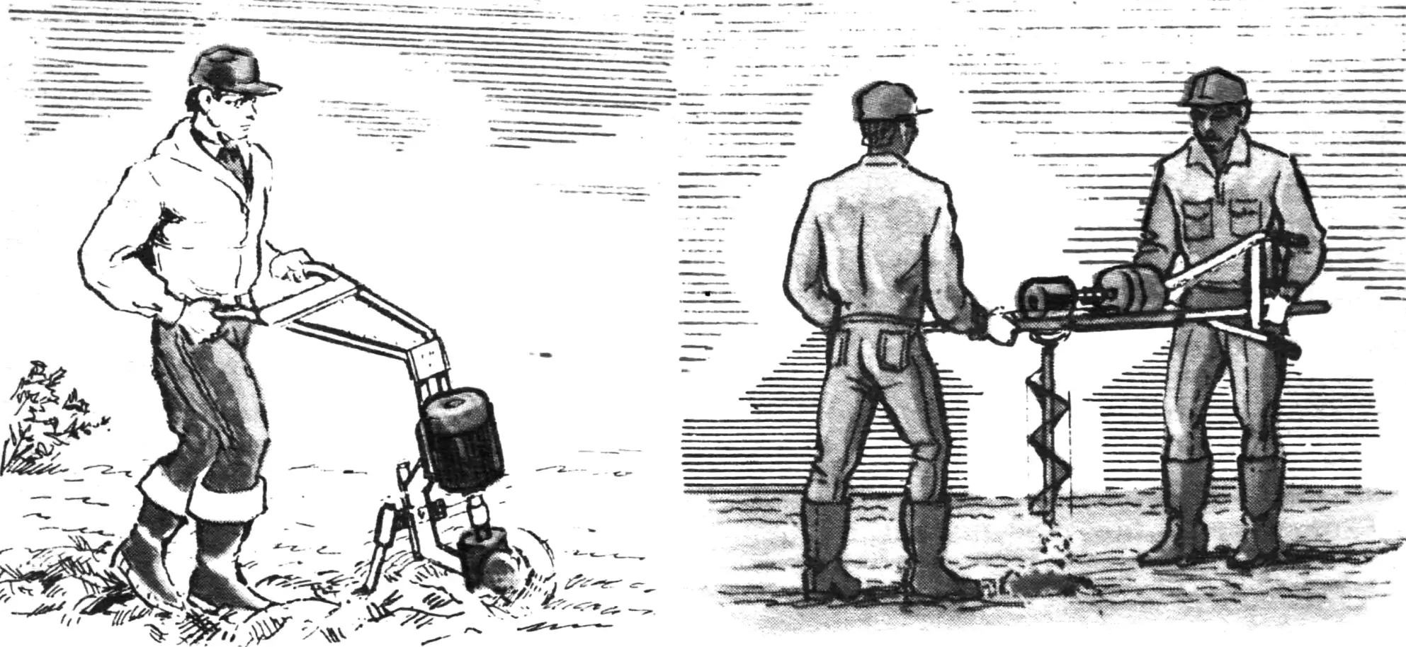
Soil cultivation with electric tillers is nothing new. Especially for owners of summer cottages, gardens and vegetable plots (see, for example, “M-K” 3’83, 11’90). And when prices keep rising, when using walk-behind tractors (not to mention scarce mini-tractors) sometimes becomes economically impractical, electric helpers on small land plots are, so to speak, beyond competition. Convenient and comparatively inexpensive, and moreover fitted with special attachments, they not only make it possible to loosen soil well, weed or hill plants, but also successfully perform a number of other useful jobs around the household.
How to make yourself such an electric helper, which if needed can also serve as a hole digger, is told in material based on publications in the Bulgarian magazine “Napravi sam”.
A well-worn electric motor, a worm gearbox from written-off equipment (an old electric cart or an equally ancient conveyor), plus scraps of water-and-gas pipes and steel sheets — that is, perhaps, all you need to make a reliable and truly universal electric helper in a home workshop. Such a tool will come in handy everywhere. But especially at a summer cottage, when doing various jobs in the garden and vegetable plot.
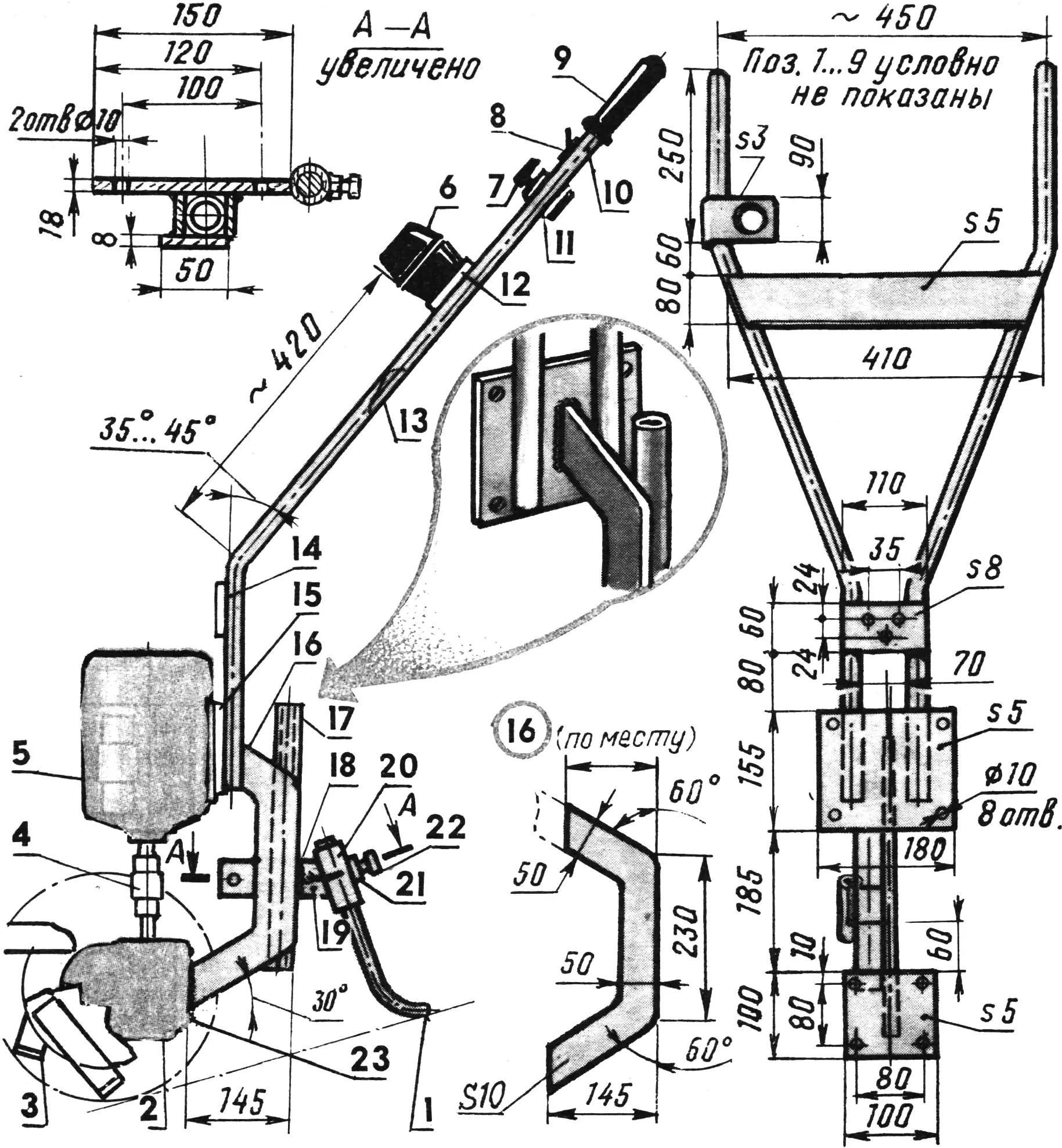
1 — drag bar (270-mm length of water-and-gas pipe 20X3), 2 — worm gearbox (i = 20…30), 3 — rotary cultivator (homemade design with six or four interchangeable blades, 2 pcs), 4 — semicircular coupling with sprocket, 5 — electric motor (220 V, 1.1 kW, 1440 rpm), 6 — capacitor unit and electrical protection, 7 — three-pole reverse switch, 8 — switch (toggle switch rated 10 A), 9 — rubber grip (2 pcs), 10 — left handle (1250-mm length of water-and-gas pipe 22X3), 11 — switch bracket (St3), 12 — upper crosspiece (St3), 13 — right handle (1250-mm length of water-and-gas pipe 22X3), 14 — lower crosspiece (St3) with three Ø 8.2 mm holes, 15 — engine mounting plate (St3), 16 — bridge base (St3), 17 — guide sleeve (360-mm length of water-and-gas pipe 33.5X3.2), 18 — strip 32X50X5 mm (St3, 2 pcs), 19 — bridge-base bracket with two Ø 8.2 mm holes (St3), 20 — drag-bar bushing (14-mm length of water-and-gas pipe 33.5X3.2), 21 — welded-on M6 nut, 22 — M6 locking bolt, 23 — gearbox mounting plate (St3). (Hole sizes and locations for the motor and gearbox are determined by the actual mounting of the latter.)
Productivity? That of the universal electric helper is quite high. Suffice it to say that a plot of 10 ares can be cultivated in less than 2 hours. And if needed, the electric tiller (cultivator) is easily converted into a hole digger. A convenient rotary–auger one (see illustrations). Only here the work is already done by two operators, not one.
The kinematic scheme of the proposed homemade electric helper is so simple that there is, I think, no point in specially drawing it. Torque from the electric motor shaft is transmitted to the input of the worm gearbox rigidly connected to it. This is done by a semicircular coupling with a sprocket. Preferably, of course, of industrial make. But a homemade rigid coupling will also do quite well here; the technology for making it has been described more than once in the pages of “M-K”.
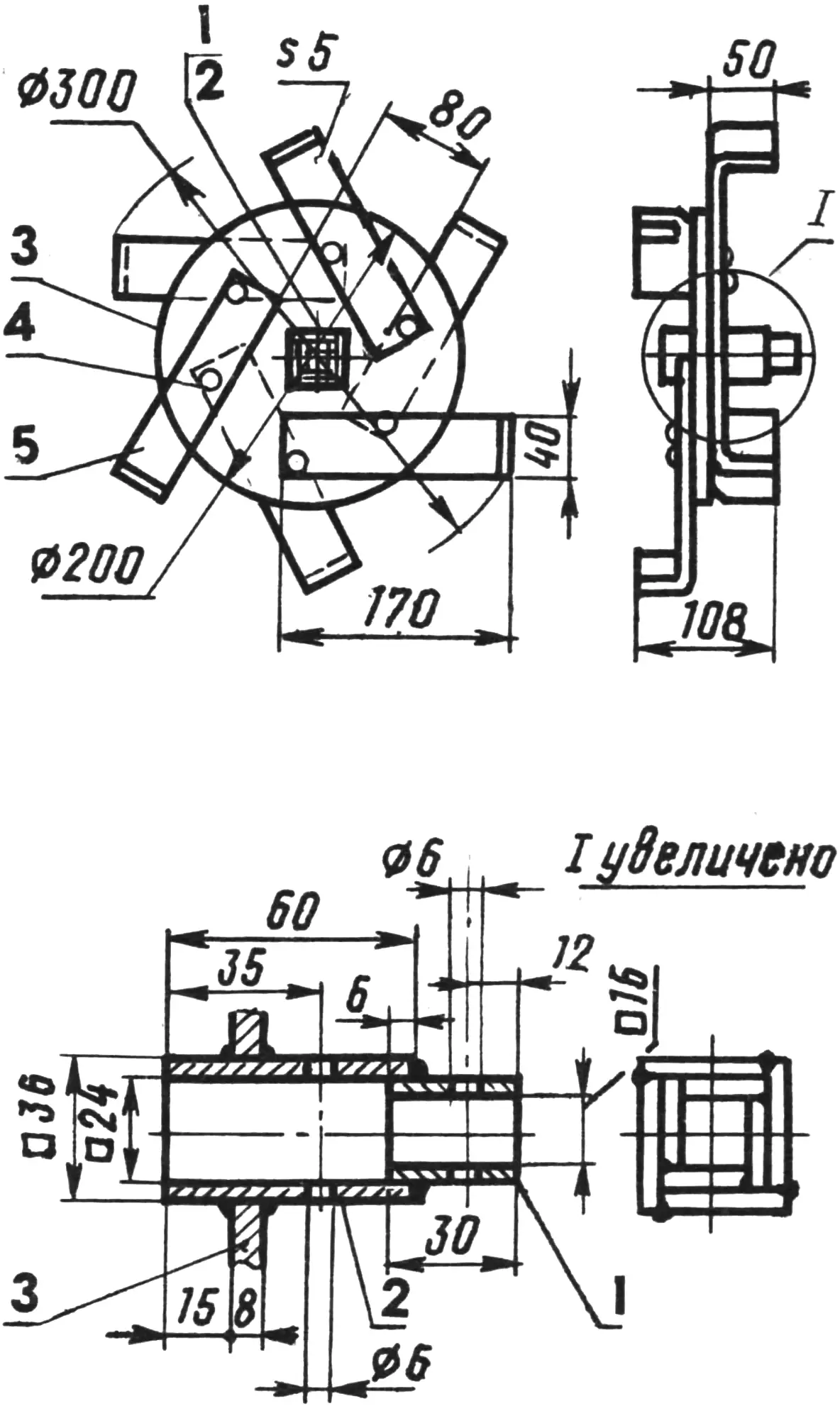
1 — strip of the square transition bushing 30X20X4 mm (St5, 4 pcs), 2 — strip of the square hub 60X30X6 mm (St5, 4 pcs), 3 — disc (St5), 4 — M8 bolt with nut, 5 — blade (Steel 65G, 6 pcs).
It is desirable to take a gearbox with i = 20…30 — to ensure a rotation speed of the working tool that is acceptable in practice; the tool is fastened firmly and reliably directly on the output shaft.
The design of the entire homemade part of the electric helper is mainly welded. The particulars of making it are shown with sufficient completeness and clarity in the illustrations given here.
The same, I think, can be said of the working tools of the electric tiller (cultivator)–hole digger. When making them, the DIY builder will not have to hunt for any scarce units, parts or materials. Everything here is quite “ordinary stock”. The steel grades are the most common ones. And only for the blades, whose work takes place under rather severe conditions, an exception is made. These critical parts are recommended to be made of Steel 65G.
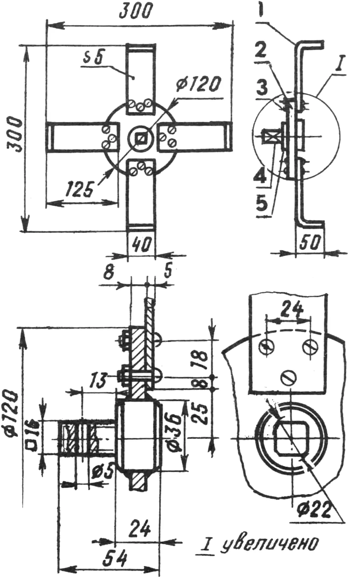
1 — blade (Steel 65G, 4 pcs), 2 — disc (St5), 3 — M8 bolt with nut (12 pcs), 4 — connecting axle (Steel 45), 5 — hub (Steel 45).
A steel strip with a cross-section of 5X40 mm serves as the blank for the blades of the rotary cultivator. From it, lengths of the required size are cut (210 mm each for the main tiller and 165 mm each for the additional one). After annealing, holes 8 mm in diameter are drilled in them for the fastening bolts; the pieces are filed and, 50 mm from the edge, bent at a right angle. The resulting blades are heat-treated: quenched with oil cooling to a hardness of 47.5…51.5 HRCe.
It should probably be noted that L-shaped blades and the technology for making them are nothing new for long-time readers of “M-K” (see, for example, the publication in No. 10 for 1983). But in the design under consideration these blades have a smaller bend radius and a somewhat larger bearing surface (40X50 mm). And the mounting angle that determines the depth of the cultivated soil layer is no longer set by special sharpening of the cutting edge and its specific orientation relative to the shank base. Its value is held firmly within the required limits thanks to the optimum placement of the blade itself on the disc: either radial or inclined, depending on the purpose of the tiller (whether it is additional or main).
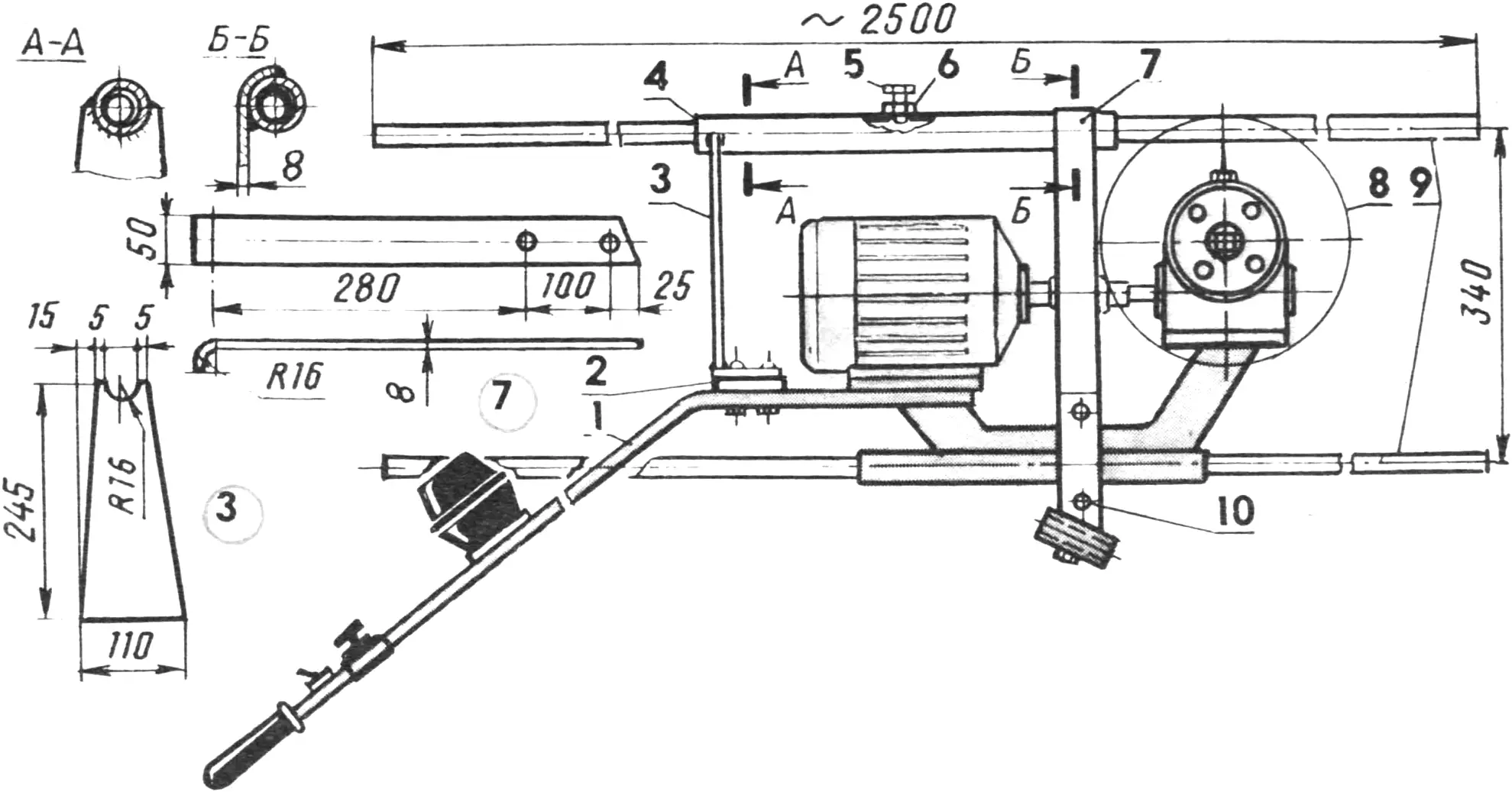
1 — electric tiller (cultivator) without working tool and drag bar, 2 — base strip (5-mm sheet, St3), 3 — frame crosspiece (St5), 4 — additional guide sleeve (435-mm length of water-and-gas pipe 33.5X3.2), 5 — M8 locking bolt, 6 — M8 nut, 7 — crosspiece strip (St5), 8 — auger assembly, 9 — hole-digger handles (2500-mm length of water-and-gas pipe 26.7X3.5, 2 pcs), 10 — M8 bolt with nut (5 pcs).
An essential point in the operation of the design under consideration is the installation and adjustment of the drag bar on which this cultivator almost constantly rests. The motor torque is not always enough, when the tiller is fully loaded, to move the cultivator forward at the design speed. And in such cases a brief unloading of the drag bar is needed, achieved by gently rocking the handles in the vertical plane.
A full set of tillers (two main plus two additional ones, inserted into square transition bushings and secured with pins) is needed for the initial soil cultivation (tilling). And for hilling row crops, as a rule, only the main tillers are used. With them one can also cut furrows — for example, for irrigation or when planting into the soil.
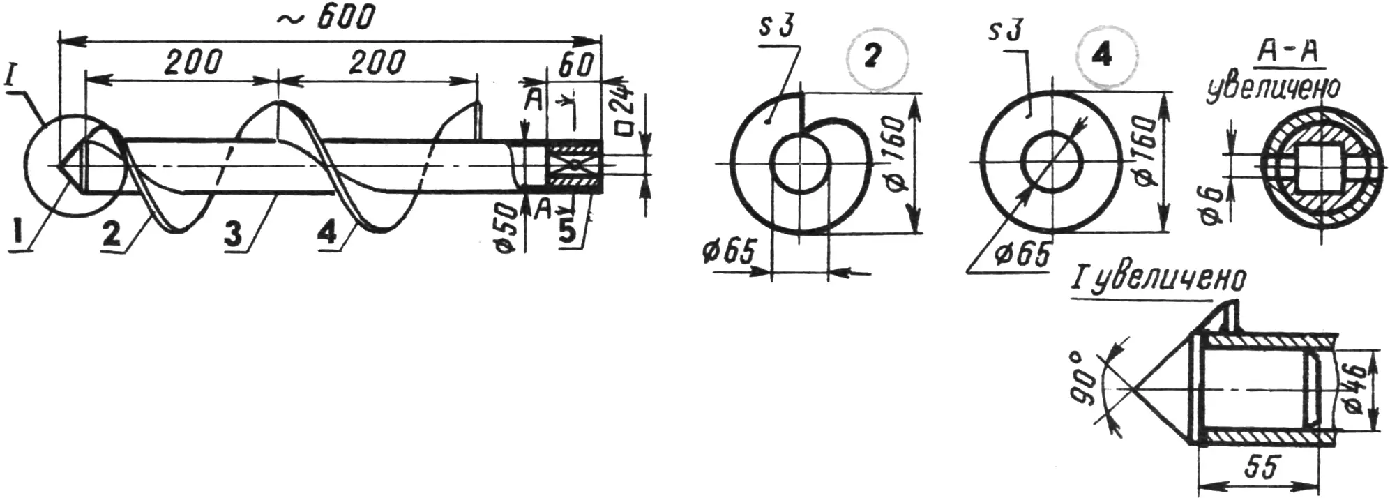
1 — tip (Steel 45), 2 — first flight (St5), 3 — shaft (575-mm length of water-and-gas pipe 50X3), 4 — second flight (St5), 5 — bushing (Steel 45).
And our electric cultivator is turned into a hole digger in just a few minutes. This is done with a number of additional elements (see illustrations). As the working tool one uses whichever homemade auger best suits the particular job (for example, digging holes for fence posts or when planting trees) — a narrow-cut or wide-cut one.
Both augers are made by the same technology, based on a welded design of a length of water-and-gas pipe and flights, the first of which immediately becomes an auger screw that differs little from the one that was described in sufficient detail in “M-K” (see Nos. 3—4/92). And the tip and the bushing by which the auger is securely fastened to the gearbox output shaft are press-fitted. The loads that arise here during work are substantial, so an appropriate material is used for the parts: Steel 45.
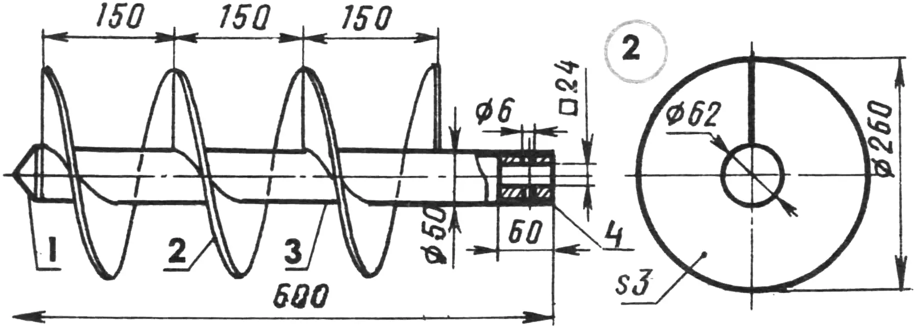
1 — tip (Steel 45), 2 — welded flight (St5, 3 pcs), 3 — shaft (575-mm length of water-and-gas pipe 50X3), 4 — bushing (Steel 45).
The electric unit is powered from a ~220 V mains supply. Moreover, for greater operator safety this is done through an isolating transformer rated 1.5 kW. Of course, one can do without it. Especially if you have a residual-current protective device (school type) UZOSH10.2.010UKHL4, manufactured by the Gomel plant “Elektroapparatura”. Compact (dimensions: 170X80X90 mm) and reliable, rated for loads up to 10 A, it will practically instantly de-energize the electric unit if a fault or insulation failure occurs in the electrical equipment.
The three-phase asynchronous electric motor used in this design operates in a single-phase connection scheme with a capacitor (star connection). Moreover, the capacitance of the latter is calculated by the formula:
C =2800Inom/Unom,
where Unom is the nameplate voltage and Inom is the nameplate operating current of the electric motor. The capacitance of the phase-shifting capacitor can also be found from the table published in “M-K” No. 2 for 1986. Incidentally, a typical circuit for connecting a three-phase electric motor to a single-phase network is also shown there. It can quite well be recommended for the electric unit under consideration as well.
But no matter which connection scheme is chosen, when working with this design one must not neglect the existing rules for operating electrical installations and safety precautions. They must be strictly observed! Moreover, it is advisable, in our view, to supplement these rules with the requirements formulated in a number of articles on homemade electric units previously published in “M-K” (for example, in the eleventh issue of the magazine for 1990), so as to fully protect the operator from electric shock.
Transport dimensions (without working tools), mm … 1400X500X600
Mass, kg … 48
Electric motor power, kW … 1.1
Electric motor shaft speed, rpm … 44
Width of cultivated soil layer, mm … 320(450)
Depth of cultivated soil layer, mm … 250(120)
Drilling depth, mm … 600
Auger diameter, mm … 160(260)
“M-K” 2’94, N. KOCHETOV
Recommend to read
 HACKSAW-THE DUO
Friends gave me a small bench set in wooden box, the kit which included the hacksaw with custom shortened paintings. When they are worn out, replacing them is not found. Helped me an...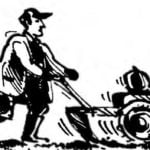 THE TILLERS WILL HELP… FILMOSCOPE
In the repair and testing of electrical tillers, not equipped with a battery, as well as type motorcycles "Voskhod-ZM" and mopeds have to ensure that the system power supply every...
