
I found the sprayers quite quickly at one collective farm and immediately set to work.
First, here is a list of the materials and parts required to build the sprayer. These include a 200 L metal barrel; steel angle sections of 90×58 and 50×50 mm; round steel tubes (32 mm in diameter), as well as square and rectangular sections (50×50 and 50×25 mm, respectively); a rigid polyvinyl chloride tube (32 mm in diameter) and a flexible polyvinyl chloride hose (16 mm in diameter); a 12 V electric pump; and a Tr 14×3 LH lead screw 400 mm long.
The equipment needed included a welding machine, an electric drill, and a regular set of hand locksmith tools.
I also had to turn two adapters on a lathe to connect the pump to the hose and the hose to the boom, a plug for the boom, and a fitting.
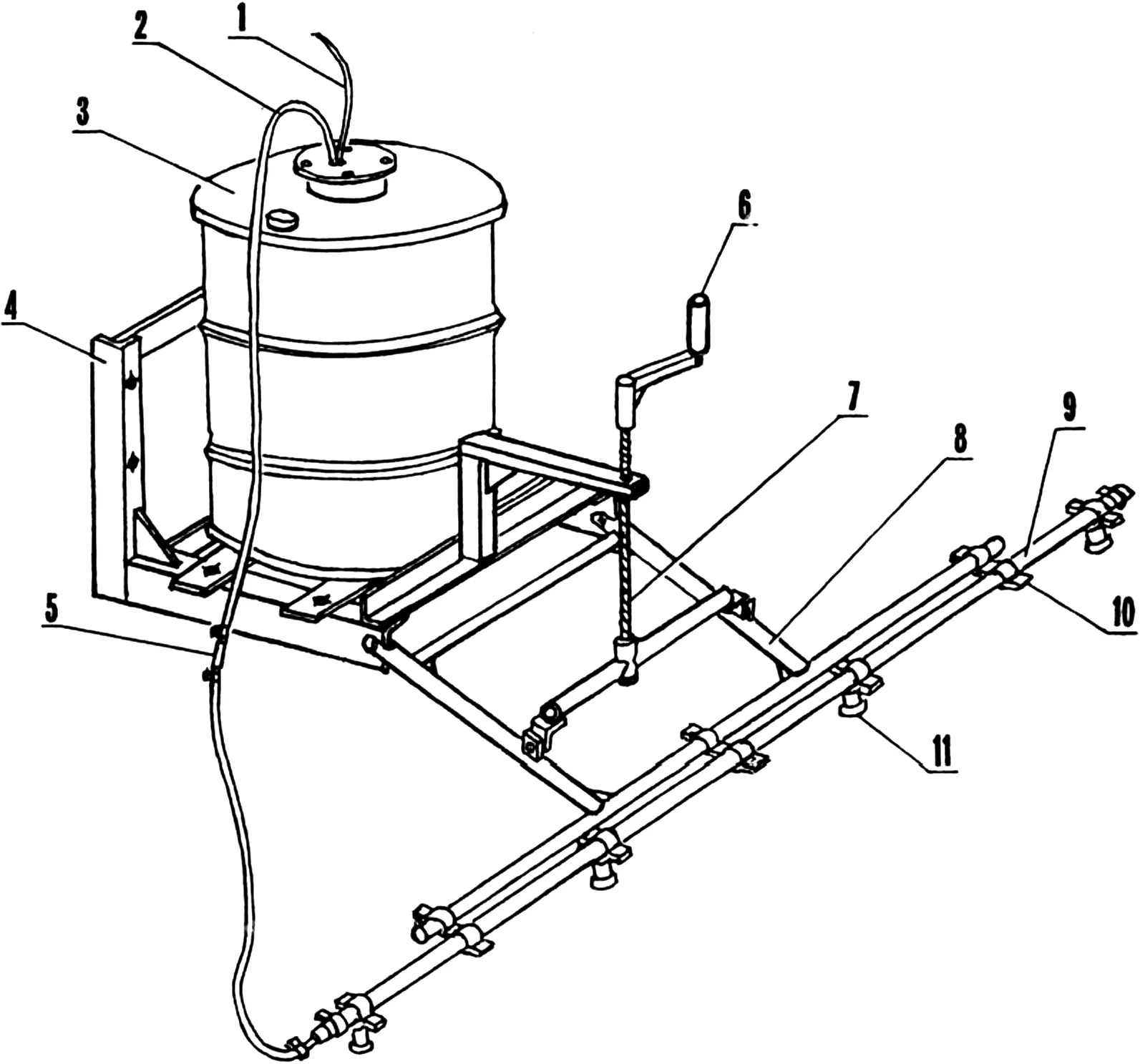
1 — electric cable; 2 — feed hose; 3 — tank; 4 — frame; 5 — connecting fitting (stainless steel, tube 12×2, L80); 6 — lifting mechanism handle; 7 — lifting mechanism screw; 8 — hinged frame; 9 — pressure boom; 10 — clamp; 11 — sprayer body (from OPSH-15 sprayer, 4 pcs.)
The sprayer is very simple in design. It consists of a sturdy frame that is bolted with four bolts to a homemade front hitch of an MTZ-80 tractor; a hinged frame; a pressure boom with four sprayers; and a solution tank.
In the tank, 50 mm from the bottom, a pump from the NC-300 12 V automotive electric washer is suspended. The pump capacity is quite sufficient for the sprayer to operate.
The sprayer is switched on from the tractor cab with an ordinary toggle switch that directly closes the positive wire of the electric cable going to the pump. Solution from the pump travels through the hose to the pressure boom and, through the sprayers, reaches the treated surface.
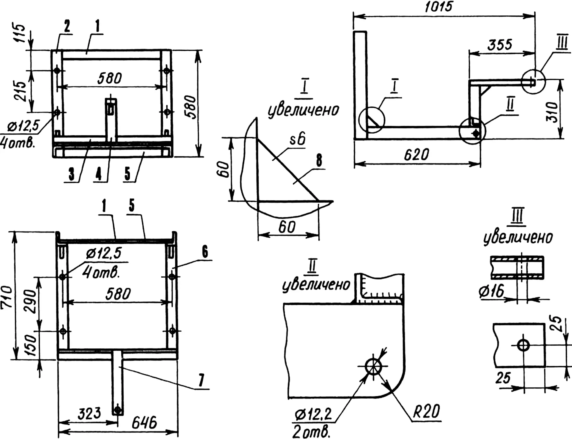
1,5 — cross members (steel, strip 50×10); 2 — bracket (angle 90×56, 2 pcs.); 3 — crossbar (angle 50×50); 4 — upright (tube 50×50); 6 — cradle (angle 90×56, 2 pcs.); 7 — arm (tube 50×25); 8 — gusset (steel, sheet s6, 3 pcs.)
The pressure boom with sprayers is attached to the hinged frame, so it is movable relative to the sprayer frame, meaning its height can be changed. For this purpose there is a lifting mechanism that allows the distance from the boom to the ground to be adjusted depending on plant height, furrow depth in the soil, and wind direction and strength.
Now I will describe in more detail the design features of the sprayer and the manufacture of each of its units.
The frame is welded from sections of steel profiles of various cross sections: 90×56 and 50×50 mm angles, 50×50 and 50×25 mm square and rectangular tubes, 50×10 mm strips, and 8 mm thick gussets.
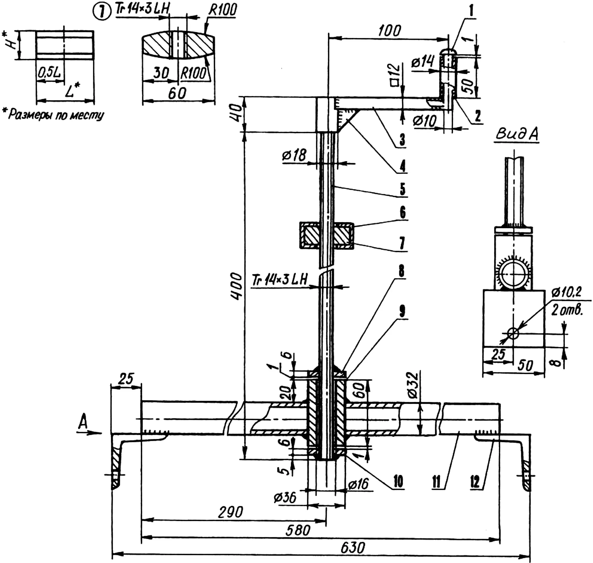
1 — handle axle (steel, rod Ø10); 2 — handle (tube 14×1.5); 3 — lever (tube 12×12); 4 — gusset (steel, sheet s6); 5 — Tr 14×3 LH lead screw; 6 — frame arm; 7 — captive nut; 8, 10 — thrust washers; 9 — thrust bushing; 11 — arm (tube 32×3, 2 pcs.); 12 — bracket (angle 50×50, 2 pcs.)
Four holes 12.5 mm in diameter are drilled in the frame brackets for M12 bolts securing the sprayer to the homemade front tractor hitch. The holes in the frame cradles are intended for four bolts of the same size that secure the solution tank.
The lifting mechanism consists of a lead screw with left-hand trapezoidal thread Tr 14×3 LH (a screw from a Zhiguli jack can also be used), a handle, and a two-arm lifting bar. The bar is welded from a thrust bushing, two arms made of 32×3 mm tube sections, and two brackets made of 50×50 mm angle sections.
Structurally, the sprayer frame is inseparably linked to the lifting mechanism, because before assembly the lead screw was first screwed into a nut set in the end hole of the frame arm, and only then was the first thrust washer welded to the end of the screw, the two-arm lifting bar was fitted on, and the second thrust washer was welded on.
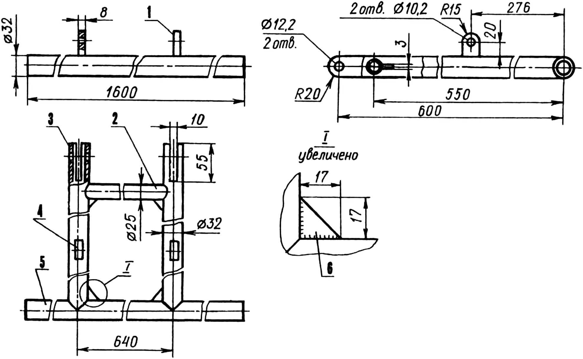
1,4 — lugs (steel, sheet s8); 2 — cross member (tube 25×2); 3 — longitudinal tie (tube 32×3, 2 pcs.); 5 — traverse (tube 32×3); 6 — gusset (steel, sheet s3, 4 pcs.)
The hinged frame is also assembled using electric welding from sections of 32 and 25 mm tubes, lugs and gussets made of sheet steel 8 and 3 mm thick, respectively. It is connected to the sprayer frame, of course, by a hinge with two M12 bolts.
By turning the screw with the handle, the lifting height of the pressure boom relative to the ground surface can be increased or decreased.
The pressure boom is a 32 mm plastic tube that is clamped to the traverse of the hinged frame with three clamps. The left (in the direction of travel) end of the boom is closed with a duralumin plug, and the right end is connected to the feed hose through an adapter. Clamps at the ends of the boom serve to seal the connections and prevent solution from leaking out.
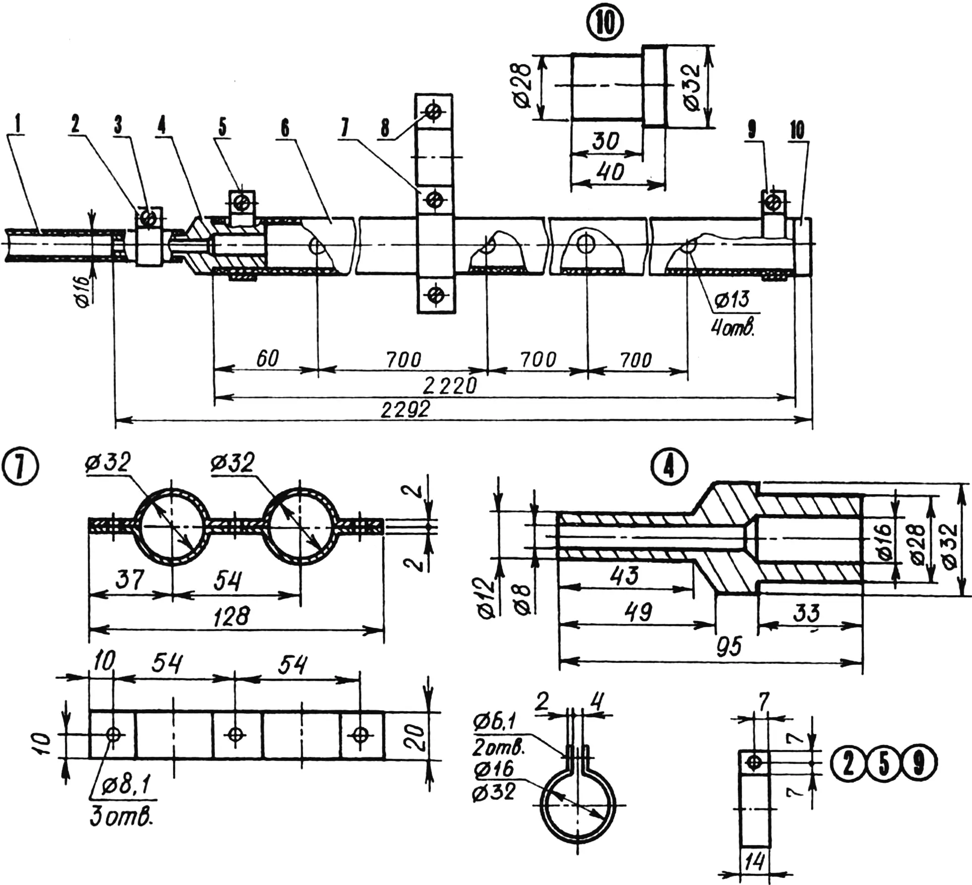
1 — feed hose (flexible PVC, tube 16×2); 2,5,9 — hose clamps (steel, strip 14×2); 3 — M6 bolt (3 pcs.); 4 — adapter (stainless steel); 6 — boom (rigid PVC, tube 32×2); 7 — clamp (steel, strip 20×2, 3 pcs.); 8 — M8 bolt (9 pcs.); 10 — plug (D16T)
Four holes 13 mm in diameter are drilled in the bottom of the boom, spaced 700 mm apart, for the sprayer bodies. The bodies together with the sprayers were taken from an industrial OPSH-15 sprayer.
The last unit of the design is the tank, made from a 200-liter barrel with thick walls. Thick walls are needed because electric welding was used when making the tank.
At the top of the barrel there is a manhole, and at the bottom there are two plate supports for mounting on the sprayer frame. The pump was inserted through the manhole into the tank and suspended there on a thin cable (from a motorcycle clutch) to a specially welded bracket.
The manhole is closed with a lid in which a hole is cut for the feed hose and the pump’s electric cable to exit. The lid is clamped to a flange welded to the top of the manhole with four M8 bolts.
It took me only a few days to build the sprayer. Then came testing. I filled the tank with water and switched on the pump. The first thing I saw from the tractor cab was a rainbow playing in all its colors on the thin film of fan spray. I clicked the toggle switch — the rainbow went out. The sprayer body is designed so that when liquid pressure stops, special seals under spring compression close off access of the liquid to the sprayers. So outside the working process not a single drop of solution reaches the ground.
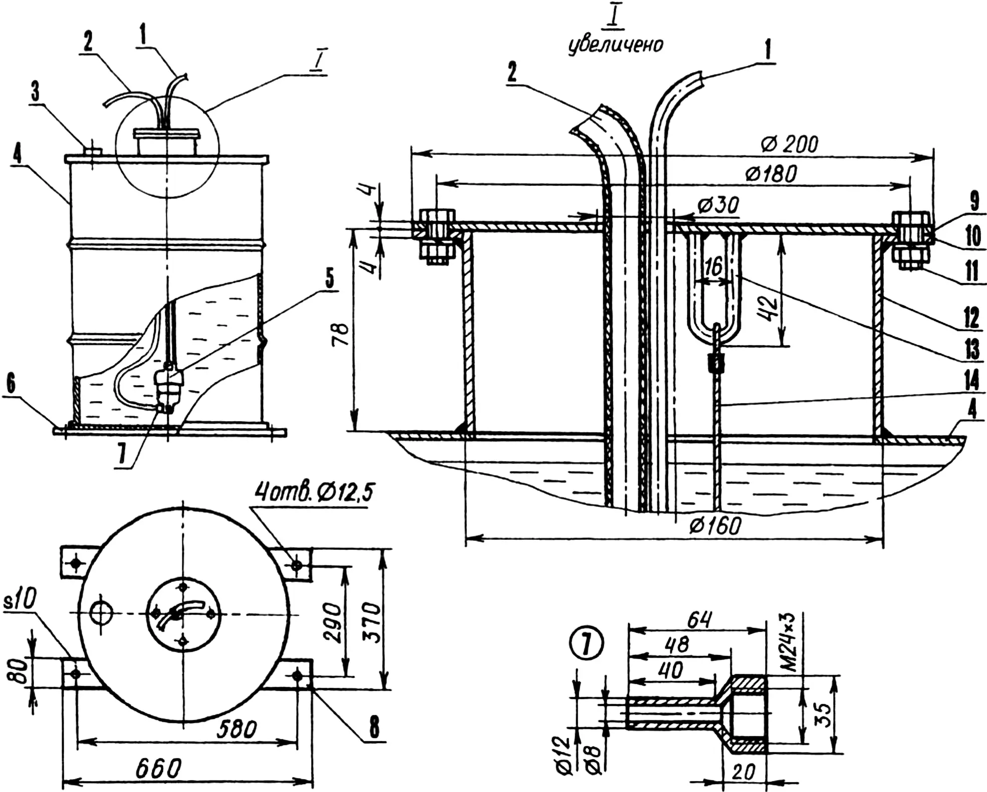
1 — electric cable; 2 — supply hose (flexible PVC, tube 16×2); 3 — filler neck plug; 4 — tank (200 L metal barrel); 5 — electric pump (NC-300, 12 V); 6,8 — supports (steel, strip 80×10); 7 — adapter (stainless steel); 9 — manhole lid (steel, sheet s3); 10 — flange (steel, sheet s4); 11 — M8 bolt (4 pcs.); 12 — manhole (steel, sheet s4); 13 — pump suspension loop (steel, rod Ø6); 14 — cable Ø2
The sprayer covers four rows of potatoes at a row spacing of 70 cm. As I already mentioned, I mount it on a homemade front tractor hitch. Behind, I couple the tractor with a cultivator-hiller. Thus, two operations can be performed at once — spraying and inter-row cultivation. This is convenient: time and fuel are saved, and the soil is compacted less by the wheels. Two operations in one pass is already advanced agronomic practice. Where agriculture receives great attention, no one is surprised by such things. Here, it is still something new for now.
By the way, the sprayer can be used not only to fight the Colorado potato beetle. Potato growers know how important mineral fertilizers are for tuber development. One of the strongest effects in potato growing comes from foliar feeding, when during tuber formation a saturated aqueous solution of mineral fertilizers is sprayed in small doses onto potato leaves.
It would take too long to describe what biochemical processes occur in the plant as a result of this procedure. I will say briefly: such feeding is very beneficial for the harvest. But again — without a special machine this technological process is impossible, and a homemade sprayer easily handles this work as well. So it works for the harvest in two directions at once!
I would also like to mention the following. The solution in the tank must be thoroughly mixed. How can this be achieved? Of course, you can stir it well through the filler neck with some long stick. But I do it differently. I cut the feed hose in the middle and inserted a connecting fitting into the cut.
Now, after pouring the solution into the tank and pre-mixing it with a clean stick, I disconnect the end of the upper hose from the fitting, lower it into the barrel, and switch on the pump. A few minutes are enough for the jet from the hose to thoroughly mix the solution to a uniform state. Then I put the hose back on the fitting and tighten the clamp. That’s it — work can begin.
The output of my sprayer (with a water supply at the edge of the field) is up to one hectare per hour. Spray quality and coverage uniformity are very high. Practically no misses or untreated spots remain.
…It is always pleasant to see the results of your own labor. And when at sunset you stand on the edge of your field, admiring the even rows of flowering potatoes, you remember how you plowed in spring, how you planted tubers in black soil without a single blade of grass, and then day after day watched how at first the first shoots timidly break through the soil, then the potato bush grows stronger and stronger, and you understand that all this was brought to life by your efforts, your hands — then there is no room left in your soul for doubts about the correctness of the chosen path, for anxieties — for anything that could shake faith in yourself, in your own strength.
Free labor on your own land — what more could a person with peasant roots wish for? Especially since today it is possible to make it more creative and less hard, to mechanize many labor-intensive operations. And every homemade implement is another step along this path, another small victory, another success in life.
“Modelist-Constructor” No. 4’2003, G. LEGOSTAEV, farmer
Recommend to read
 REPAIR IT YOURSELF!
A small speck of rust on the wing in a few weeks darkened, and then turned into a hole with ragged edges. Avtostantsii the sentence was harsh - the wing needs to be changed. Preliminary... WHAT IS NOT A SHOCK!
Usually furniture door furniture is hung on special hinges. They have one drawback — when you close the door slams. To prevent this from happening, offer points of contact to glue pieces...
