 Those who contain in the household livestock and poultry without grain reserves is not enough. Grain can be stored for a long time (in one of the magazines I read that in the tomb of a Pharaoh found the amphora with the wheat seeds were such that even wiseway). But that grain use for animal feed with greater benefit, must be pre-ground or at least crushed. But the grind, even large ones, unfortunately, under normal conditions for a long time can not be stored with it and the quality loses, and’t go rancid, and it infest some bugs, worms. So grinding is necessary in small amounts, and therefore quite often.
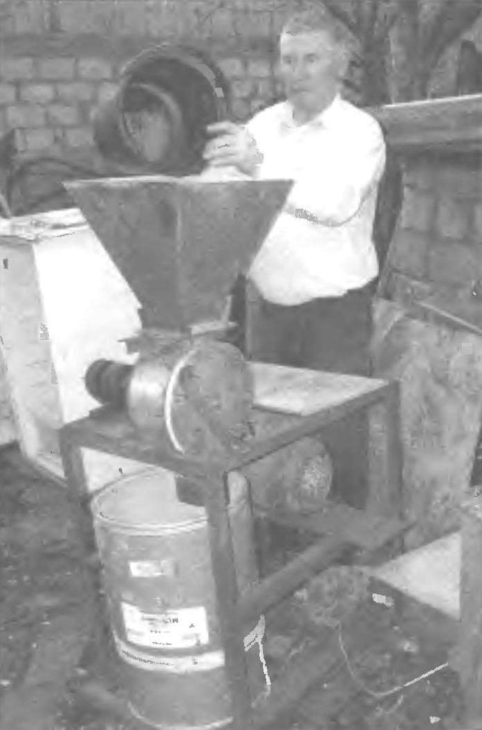
Here’s the problems: industrial mill such amounts are simply not linked. Earlier rescued from farms or farmers, but the first collapsed and a second, Pomaia, switched most of them to trade.
But because the owners have to acquire some no, but private mills, Shellers or sertraline who industrial manufacturing and who’ll do it. The second way I went.
Design crusher, in General, simple, can say even simplistic. All components and assemblies are mounted on a simple rectangular frame, welded skeleton which for the most part made from a steel angle 50×50 mm. the Support platform of the frame under the motor and bearing of the drive shaft is made of steel 6 mm sheet, and a cargo area-table — of asbestos-cement sheet with a thickness of 10 mm.
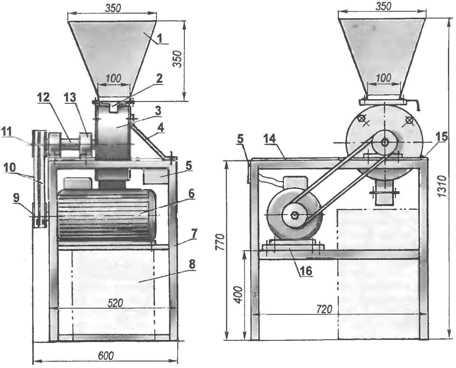
The layout of the crusher:
1 — receiving hopper; 2 — slide valve; 3 — worker node; 4 — brace; 5 — control panel; 6 — elektrodvigatel (3-phase, N = 3 kW, n = 3000 rpm); 7 — frame; 8 — container for ” hog ” fuel; 9 — drive pulley; 10 — drive V-belts (profile B, 2); 11 — slave pulley; 12 — drive VAG.; 13 — block bearing 307 in the housing (2); 14 — load platform (asbestos cement sheet 10 s); 15 — bearing area of the shaft (steel sheet s6); 16 – the supporting base of the motor (steel sheet s6)
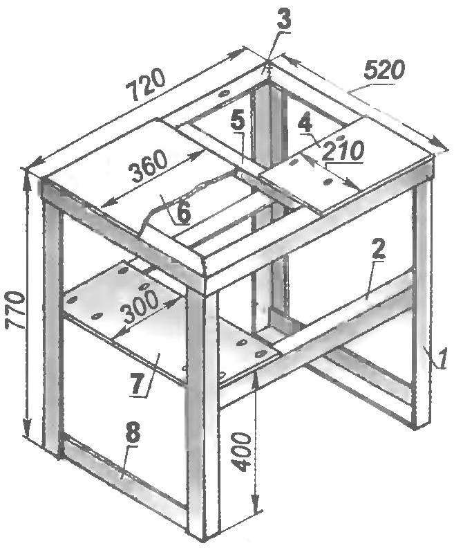
Frame (holes in base plates are drilled in place):
1 — front (area 50×50,4 pieces); 2 — drawer side frame (area 63×63,2); 3 – upper rail backbone (area 50×50); 4 — supporting platform drive shaft; 5 — the upper crossmember (area 50×50); 6 — load platform; 7 — support platform of the motor 8, the lower cross member (area 50×50, 2 PCs.)
The crusher motor power 3 kW rotation speed 3000 rpm operates from a three phase AC network with voltage of 380 V.
The transmission of torque from the engine to the drive shaft is made by two V-belts profile B. double-strand Pulleys, and a motor shaft diameter smaller, because the speed of rotation of the shaft, slightly larger than the motor, about 3500 rpm.
The tension of the belts by moving the motor along with the platform on the intermediate cross members (cargo) of the core frame. The engine on the ground and the ground on the crossbars are fixed with four bolts M10 each
Drive shaft one piece, stepped, turned himself from steel 45. On the frame it is mounted on two supports in ball bearings No. 307, each installed in its housing.
The cantilevered shaft, that is, the supports located in the median part. On one end of the shaft is mounted a driven pulley, and the other hammer rotor. And the pulley, and the rotor is mounted on the shaft by tight fit with key connections.
The hopper is made of steel sheet with a thickness of 1 mm. It has the shape of an inverted truncated regular pyramid with bases 350×350 mm and 100×100 mm and a height of 350 mm. His neck (a narrow base) edged welded steel corner 25×25 mm.
The same trim has a boot (upper) hole of the housing of the crusher. When building the edging are joined through the rubber strip and hopper and the housing are attracted to each other by four M6 bolts through corresponding pre-drilled in the corners of the trim holes.
Sides — the outside of the package crusher — the cut (130 mm) thick (6 mm) stainless steel pipe with outer diameter of 270 mm. it is inserted Inside the stator — cut another pipe (of the same length and thickness), the outer diameter of which corresponds to the inner diameter of the first. In the pipe joint made from both sides four threaded deaf holes (socket) – M8, which are screwed into the studs. By means of pins attracted to the hull side flanges, and the studs serve as a kind of dowels that allow the stator to rotate relative to the pipe shell. One flange is deaf and the other with a hole for the shaft with a sleeve. The case flanges are installed on Hermetica.
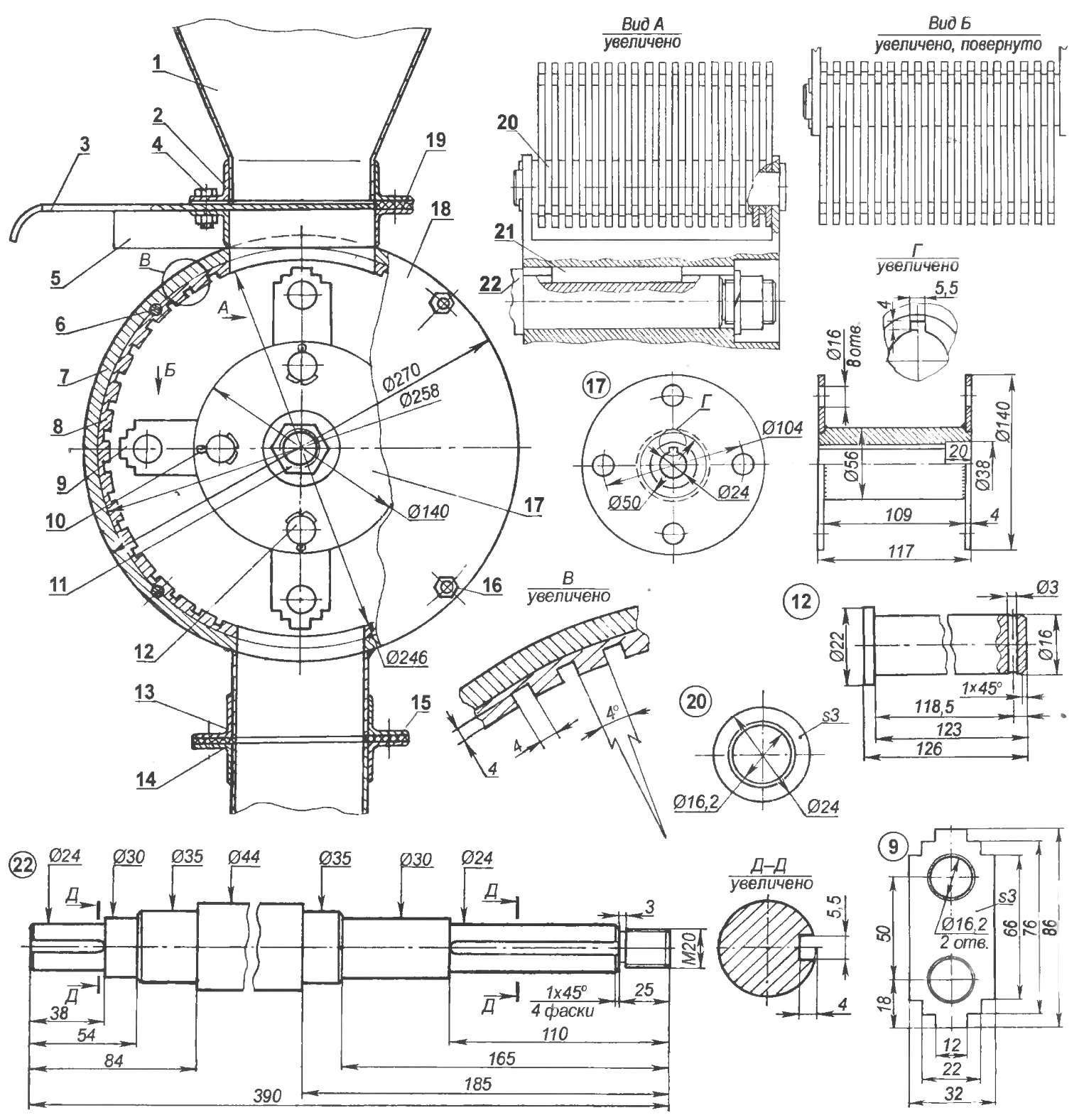
Working site of crusher:
1 — hopper (sheet s1); 2 — trim cap hopper (area 25×25); 3 — slide valve (sheet s1); 4 — M6 pinch bolt (8 PCs); 5 — piping the feed opening of the housing (25×25 area): 6 — pin M8 (8 PCs); 7 — outer shell (tube Ø270×6); 8 — ribbed stator (tube Ø258×6); 9 – hammer (sheet s3, hardened to HRC 45-47,72 PCs.); 10 — cotter pin Ø3 (4x); 11 — nut M20 spring washer; 12 — axis mallets (round 22,4 PCs); 13 — tying short tube (25×25 area); 14 — binding of a long tube (25×25 area); 15—gasket (rubber, sheet s3); 16 — nut M8 flange mounting (8 PCs.); 17 — hammer mill rotor; 18 — flange (sheet s5, 2 PCs.); 19 — gasket (rubber, sheet s3); 20 —remote washer (sheet s3 72 PCs ) 21 — key; 22 — drive shaft
On the inner surface of the stator sliced transverse grooves with a cross section of 4×4 mm (to late of grain).
At the bottom of the hull made another rectangular hole (same as above) and unloading with flexible exhaust pipe — short and long. The joint between pipes is made the same as in the neck. While unloading a barrel ” hog ” fuel in the lower pipe off, and when poured into the bag — connected. The joint besides serves as a flange over which the bag is knotted, so that he flew off the pipe.
The housing is tack welded to the crossbars of the frame frames.
The most complicated node in the mill grinder — hammer mill rotor. To invent it anew I did not and made in the image and likeness of those that are in a similar, mass-produced machines, reducing only the length of the hammer (so they fit in the case), but by increasing their number .axis.
In addition, the hammers and the stator housing gave to a heat treatment, where they tempered to 45 — 47 units HRC.
When assembling the blocks hammers washers and remote install them in the rotor so that the gaps between the hammers alternated on adjacent axes.
After the landing of the rotor on the shaft snapped another nut with a spring washer and thread on the end in several places scored by the core.
Adjusting the flow of grain from the hopper to the rotor is performed using the sliding damper fitted between the trim of the neck of the hopper and the feed opening of the housing. But very often after you switch the mill, pour the grain from the bucket or even bag — power and rotor speed enough to shred the mass of grain “on the move”.
In conclusion, largely due to the simple design of the crusher in it, I’m the grinding of any dry substance for preparation of fodder mixtures from hay to cake.
V. KURAKIN, Saransk
Recommend to read
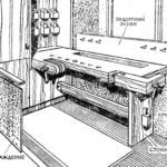 WORKSHOP IN A CITY APARTMENT
Loggia, balcony — a kind of additional area of the apartment. However, it is not particularly large, but how efficiently we use these "extra" square meters? After all, a reasonable...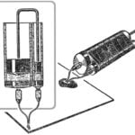 DISPENSER FOR EPOXY RESIN
Epoxy adhesive, as is known, consists of two components: resin and hardener. Before use, the components are mixed in the ratio of 8 : 1 (by volume). It's easy, especially when the...
